high-quality audio and video applications in wireless phones requires faster sampling rates, wider dynamic range, and larger memory. Even in the limited space of a car, a global positioning system (GPS) receiver that stores DVD information with multi-channel audio and high-resolution location display requires high-quality audio and video.
The convergence of consumer applications highlights the importance of system-level integration, which is the integration of RF, mixed signals, high-speed interfaces, power management, memory, and high-performance processors. To reduce size, cost, and power consumption, these devices are made using system-on-chip (SoC) or single-package system. As the number of functions and various cores increases, the number of pins is also increasing to meet the requirements of digital control lines and data lines.
Industry-Specific Test Requirements
As SoCs and SIPs in high-volume consumer industries become more complex, the fundamental requirements of low cost versus long device lifecycle become more challenging. Consumers demand increased performance at the same or lower cost, and often demand new improvements. Therefore, components must be tested thoroughly and at low cost and extremely fast.
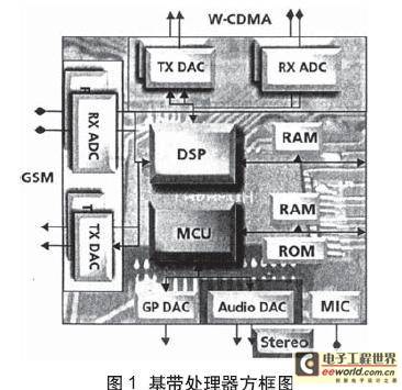
Providing more parallel processing capabilities in testing while greatly reducing the throughput overhead of ATE architectures may properly address the additional time issues associated with testing increasingly complex devices. In addition to the above two measures, the resolution and accuracy of ATE hardware must be guaranteed to address the emerging analog core challenges in leading-edge consumer devices. Highly integrated SoC devices
with audio DACs and ADCs
, such as the wireless handset baseband processor shown in Figure 1, have multiple functional blocks with different performance levels built in, and are under the dual pressure of specifications and test time.

When discrete CD-quality DACs and ADCs were used in the consumer market, the ATE-related test costs were manageable because of the initiative to increase device prices. When CD-quality cores are integrated into SoCs, the increase in device prices can no longer offset the increase in ATE test costs due to the increase in test time caused by the additional functions and the negative impact on the cost of test (COT). Audio Core
Test Time Derivation Example
For mixed-signal dynamic testing, it is critical to prevent spectrum leakage in the spectrum generated during the analysis process. Therefore, the following relationship must be satisfied:
M/N=Ft/Fs
Where M is the number of capture cycles; N is the number of sampling points; Ft is the test signal frequency; Fs is the sampling frequency.
For low-fidelity audio devices, such as microphones with ADC inputs or headphones with DAC outputs, an 8KHz sampling rate is used, which is equivalent to a 4KHz bandwidth. If the test signal frequency is 1.03125KHz, 66 cycles can be captured relative to an 8KHz sampling rate and 512 points. The sampling time is equal to the number of sampling points divided by the sampling frequency, which is 64ms. Audio testing requires more than 10 tests, including multiple gain states; idle channel noise (ICN), crosstalk (XTALK) and intermodulation distortion (IMD). This means that even for a simple core, the total test time is 650ms. The
test overhead of transferring 20-bit sampled data from the ATE's analog or digital capture memory to the workstation is also considerable. To determine the amount of data to be transferred for analysis, multiply 20 bits by the number of sampling points N, and then multiply it by the number of measurements of the test core. In this example, 20 bits × 512 points × 10 measurements total 102400 bits. Assuming a 1MB bandwidth between the analog module and the workstation, the transfer time to test the DAC core is approximately 100ms. The digital capture memory transfer overhead is also 100ms at the same bandwidth. Therefore, for voice quality DAC and ADC testing, the 200ms transfer overhead increases the total test time to 1500ms (650ms + 650ms + 200ms).
Parallel Test Overhead of ATE Architecture
To further illustrate this issue, consider the impact of a surround sound audio processor on test time. AC3 digital audio provides 6 analog outputs: front L/R; surround L/R; center speaker and subwoofer. From an analog point of view, these devices require a combination of high dynamic range and parallel test.
CD quality dynamic range and bandwidth require a higher sampling rate. Using the above formula and substituting Fs = 4.8KHz, the sampling time is 10.7ms. Taking into account hardware setup, test stabilization and other overheads, the test time is 15ms. Taking into account the number of measurements of more than 10 times, the total test time rises to 150ms. Thus, for each position with 6 channels, the serial test implementation will take 900ms.
The 4-test point implementation can take full advantage of the parallel testing of multiple waveform digitizers. However, data transmission is still serial in multi-test point testing, and the transmission overhead is cumulative. Therefore, even with 4 waveform digitizers, the 4-test point test implementation takes 900ms + 4 × 600ms = 3300ms.
Multi-standard wireless baseband processors
Wireless devices set multiple standards in the same mobile phone. To support these standards, chipsets often have redundant baseband analog converters and RF transceivers. For example, in audio surround sound processors, the numerous analog cores in wireless baseband processors have a huge impact on test time. The main challenge in testing these devices is how to set up sufficient parallel tests in the analog test hardware to obtain the efficiency of multiple test points. The
baseband processor block consists of orthogonal (I/O) transmit (TX) DAC and receive (RX) ADC pairs. In 2G to 2.75G GSM/GPRS/EDGE technology, the carrier channel spacing is limited to 200KHz, resulting in low-frequency zero IF. W-CDMA uses 5MHz channels, which corresponds to a wider bandwidth.
The RX and TX paths usually require full dynamic testing, including signal pair distortion (SND), CIN, and XTALK. I/Q pairs DAC and ADC also require gain matching and phase matching testing, with indicators specified within 0.1dB and 3 degrees of high accuracy respectively. The requirement to ensure channel isolation during transmission leads to additional out-of-band (OOB) attenuation testing of the DAC. Adjacent channel power ratio (ACPR) can confirm the degree of channel isolation, and for W-CDMA DACs, the OOB frequency is tested up to 10MHz. [page]
High-definition video encoder
Current SoC devices support multiple video input standards. Traditional NTSC or PAL devices are equipped with super video CS-VIDEO and composite analog outputs. Supporting HDTV requires 3 additional outputs to provide signals that comply with YPrPbHDTV (EIA-770.1-3). 6 video DACs are required to prepare all the above outputs: 2 for S-Video, 1 for composite output, and 3 for RGB.
Although digital video standards require a maximum interface speed of 74MHz, the analog bandwidth required to test DAC performance is approximately 8MHz with a resolution of 10 to 12 bits. Typical test items for a single video DAC include integral nonlinearity (INL), differential nonlinearity (DNL), and SND measurements. The picture quality of HDTV systems is determined by the relative accuracy of the DAC output, and additional tests must be performed on output gain and phase matching. The total test time of an embedded digital video device is directly related to the number of parallel digitizers available for testing. The number of video DACs under test is usually more than 6, and due to the lack of tester resources, it is essential to establish a serialized test plan.
Parallel Test Plan
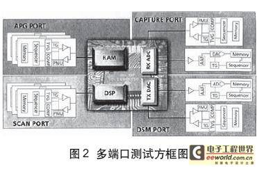
Although reducing the overall COT is affected by many variables, implementing multi-point testing and parallel testing to improve throughput is undoubtedly the main method. The latest generation of ATE systems uses a multi-port architecture to support a group of tester resource structures that match the functions of the device under test. The
two main functions to achieve this goal are per-port timing generators, which match the frequency of the test core; and per-port sequencers, which can work in different test modes and automatically execute sequence instructions. The multi-port per pin solution goes one step further than the above solution and subdivides the granularity of both digital and analog resources of the ATE system to each pin. An example of the necessary resource structure for testing a typical SoC includes: DSP used as a communication processor, memory, and ADC and DAC interfaced with analog IF or RF front end. In this case, the digital pins are configured in scan mode to test the DSP core (see Figure 2).

Because the test system is segmented on a per-pin basis, the application software can automatically manage most of the control of multiple test points by copying the image of the test vector and the sequence on the pin used for each test point.
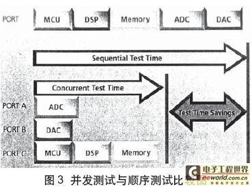
Concurrent testing is an extension of multi-port testing, allowing these cores to be tested in parallel. Of course, each core in the device should be independently accessible and controllable by the ATE system and can operate independently. Modifying the pure sequence flow of serial testing of each device core to a sequence flow of parallel testing of multiple device cores can greatly reduce test execution time (Figure 3).

In large-scale devices (such as wireless baseband SoC processors), there are countless analog cores, and testing these cores in parallel requires a large amount of analog resources. If calculated according to 4 test points, full parallel and concurrent testing style, 28 digitizers are required, which is difficult to achieve in current ATE systems.
A new module architecture
Testing the various analog cores used in current consumer devices requires a highly parallel, low-overhead solution. If several module functions are combined in each module, the space occupied by each analog module can be reduced accordingly, so that more space is left for the necessary digital modules. A module with 8 independent Arb or digitizer units built in has the advantage of flexible configuration: it can be used as a digitizer unit only, or a combination of digitizer and Arb units.
Reducing the COT of consumer device testing requires not only solving the parallel test solution of the ATE test system, but also reducing the ATE overhead caused by parallel testing. Multi-core is the main feature of current SoC consumer devices. When improving the architecture of ATE hardware, the above two factors should also be considered to obtain the best test solution.
Previous article:Lithium battery performance and safety testing solutions
Next article:Design of automatic test system for DC servo motor based on Delphi
- Keysight Technologies Helps Samsung Electronics Successfully Validate FiRa® 2.0 Safe Distance Measurement Test Case
- From probes to power supplies, Tektronix is leading the way in comprehensive innovation in power electronics testing
- Seizing the Opportunities in the Chinese Application Market: NI's Challenges and Answers
- Tektronix Launches Breakthrough Power Measurement Tools to Accelerate Innovation as Global Electrification Accelerates
- Not all oscilloscopes are created equal: Why ADCs and low noise floor matter
- Enable TekHSI high-speed interface function to accelerate the remote transmission of waveform data
- How to measure the quality of soft start thyristor
- How to use a multimeter to judge whether a soft starter is good or bad
- What are the advantages and disadvantages of non-contact temperature sensors?
- LED chemical incompatibility test to see which chemicals LEDs can be used with
- Application of ARM9 hardware coprocessor on WinCE embedded motherboard
- What are the key points for selecting rotor flowmeter?
- LM317 high power charger circuit
- A brief analysis of Embest's application and development of embedded medical devices
- Single-phase RC protection circuit
- stm32 PVD programmable voltage monitor
- Introduction and measurement of edge trigger and level trigger of 51 single chip microcomputer
- Improved design of Linux system software shell protection technology
- What to do if the ABB robot protection device stops
- Keysight Technologies Helps Samsung Electronics Successfully Validate FiRa® 2.0 Safe Distance Measurement Test Case
- Innovation is not limited to Meizhi, Welling will appear at the 2024 China Home Appliance Technology Conference
- Innovation is not limited to Meizhi, Welling will appear at the 2024 China Home Appliance Technology Conference
- Huawei's Strategic Department Director Gai Gang: The cumulative installed base of open source Euler operating system exceeds 10 million sets
- Download from the Internet--ARM Getting Started Notes
- Learn ARM development(22)
- Learn ARM development(21)
- Learn ARM development(20)
- Learn ARM development(19)
- Learn ARM development(14)
- [Repost] This article tells you the difference between Ethernet and broadband
- The CC3200 LaunchPad crashed before I even got it warm?
- TMS320F28377S Study Notes 3 Building a fully portable CCS9.3 project
- Recruiting part-time lecturers in motor control related majors
- It is recommended to merge the ATMEL and PIC microcontroller sections
- TI TMS320C6678 Evaluation Module
- IoT wireless communication data transmission module: multi-host gateway working mode, understand it in one article
- [RT-Thread reading notes]——The definition of threads and the implementation of thread switching
- How to read and write attributes through the characteristic uuid in sdk!
- MSP430FR5994 Hardware SPI Exception

 The authoritative guide to AR development: Based on AR Foundation (Wang Xiangchun)
 ICCV2023 paper summary: Vision and Audio


 京公网安备 11010802033920号