Share an electronic touch organ circuit
Source: InternetPublisher:elleny Keywords: Audio circuit music equipment Updated: 2025/01/07
The electronic touch organ is a fun musical device that produces very pleasant musical notes in response to the touch of fingers on special touch-sensitive electronic pads or buttons.
However, modern organs are very expensive, often making them out of reach for most people. Low-cost options lack performance and are in the form of polyphonic organs, which, while working like polyphony, tend to be relatively minimal reed-based devices controlled by small blowers.
The title polyphonic organ originates from the fact that the bass association is through the control keys that produce the correct note. The lowest priced organ is probably the so-called monophonic organ (only one note can be played at any given time), which is usually a little more than pocket-sized and is played using a stylus.
The first obvious development essential was to prepare an improved keyboard setup, as the functionality of the stylus can be rather cumbersome. However, the £40 price tag for a full keyboard could not be justified. As you can see from the pictures, the new keyboard is still touch type, but has now been shaped so that the organ can be played simply by touching the appropriate pads, just like a full-sized instrument.
Additionally vibrato is provided, which is also activated and deactivated via a contact pad, and controlled to adjust the vibrato depth. Another enhancement is the precision of tuning, in earlier instruments the keyboard was different inside as there was only one resistor that was used to increment between each note. In the innovative model the tuning on the keyboard is taken to a greater advantage by using a pair of resistors (in series or parallel if necessary) to get the closest accurate value of resistance.
Finally, the instrument has several voices or stops, greatly increasing the choice of music that can be produced. This little organ is very affordable to construct and really should give you great satisfaction, both musically and electronically.
Construction
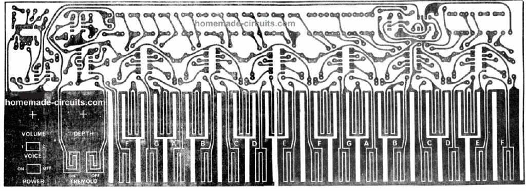
The keyboard structure of this electronic touch organ is printed directly on the PCB, which also houses the other components.
Since the copper tracks of a keyboard can easily corrode from the constant touch of your fingers, it is very important that your PCB is tinned or shielded with some form of plating to avoid tarnishing.
Start construction by mounting the LM380 in place, then attach the small heat sink heatsinks in place, as shown, to both areas of the IC. Solder them to pins 3, 4, 5 on one side, and pins 1, 2, 3, 4, 5 on the other side.
10, 11 and 12.
This should be done first as this area of the PCB may have little space. When the various other components have been soldered in place. Connect the two wire links and then "place the low height components on the board as shown in the overlay. Place the rest of the ICs last and be extra careful not to overwork the CMOS before installation
IC. Check the polarity of polarized components such as ICs, capacitors, and diodes before soldering them in place.
To avoid having to see the screws on the keyboard, use five-minute epoxy glue to secure both switches in place. Apply some wood or metal to the rear of each mounting hole for increased gluing surface area and greater durability.
Connect the potentiometers and wires as specified in the overlay diagram to complete the PCB. The entire unit must be tested at this point to ensure all notes and functions operate effectively before installing into a suitable enclosure
Design Features
As I said before, the basic feature is to use a finger touch method rather than a "probe" type implementation of the keyboard. Therefore, some technology must be associated with each key to recognize that it has been touched.
Touch control of the touch organ is usually affected by capacitive, resistive or 50 Hz injection procedures, with capacitive technology being the most effective of the three. This is usually the most expensive and therefore not employed. 50
The Hz injection method is actually just as complicated, so the resistor method is considered the only truly useful method from a price tag perspective.
Since the keyboard is currently played by fingers, it also has to be larger than normal, if still not as large as a full-fledged keyboard.
In the original theory, the OM802 IC was used as a tone oscillator. This was replaced by the 555 timer IC as it was cheaper and turned out to be more reliable.
There are several outputs available, a sawtooth wave and a narrow pulse.
Both outputs are used in our layout to provide a diverse sound to the instrument. The sawtooth wave is filtered through a simple RC filter to get rid of several harshness due to the harmonic framework, and the resulting tone has a vibrant, flute-like audio quality.
The pulse output is combined to the sawtooth using a resistive attenuator, but is not filtered in any other way. The tone has a string-like noise.
Filtering has been kept pretty basic from a price point of view. If the user wishes, the person can test various filters to get a variety of sounds.
For traditional pipe organs, stop filtering is done in each octave of the organ to avoid unwanted pitch and level changes at unique frequencies.
With the 2 octave cycle of this organ, several changes in pitch and level must be identified within the keyboard range when using simple filters.
Because of the attenuating filter, a lot of gain has to be available in the audio output stage, hence, an LM380 op-amp is used in the audio output stage to operate the speakers in the best possible manner.
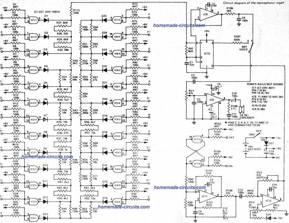
Circuit Diagram

How it works
How the organ is operated will be explained by looking at the 5 parts it is composed of independently.
These are:
(a) Keyboard
(b) Oscillator
(c) Filter
(d) Output amplifier
(e) Tremolo circuit
(a)
Keyboard: Compared with traditional touch organs, the keyboard is controlled by finger skin resistance rather than probe control. Each key has a CMOS gate, connected exactly where the two inputs of the gate tend to be connected together, and is controlled by 4.7
The M resistor is connected to the positive power supply.
Once the button is pressed, the input to the gate is pulled low (100V) through the 0 k resistor, causing the output of the gate to go high. This pulls the rest of the resistor string high across the diode.
So by selecting and touching the various keypads we will 2 oscillator pins 6 and 555
Resistors of varying levels are connected between the positive supply, thereby activating it and varying the frequency determining time constant of the circuit.
(b) Oscillator: The oscillator relies on a 555 timer, capacitor C1. Capacitor C1 along with resistor R113 is charged up through a part of the resistor string (such as a keyboard). If pins 2 and 6
The voltage at 555 reaches the level set at pin 5. The capacitor is forced to decompose rapidly through R97 and the blocking transistor connected to pin 7 of the 555.
Once the voltage across C1 drops to half the voltage set at pin 5, the internal transistor of IC 555 turns off and allows the capacitor to charge again, thus continuing the cycle and creating a sawtooth wave across the capacitor.
This waveform is rich in harmonic material but is produced at a high impedance level. Therefore, a unity gain buffer (IC8) is applied to offset the output loading of subsequent circuit stages.
A second output of a narrow pulse waveform is available at pin 3 of the 555 and is used to create a second tone for the instrument.
(c) Filters: Several different filters have been experimented with, but from a cost standpoint it was absolutely difficult to verify anything other than a basic RC filter on the saw teeth, which gave a surprisingly relaxing flute-like result. Since the narrow pulse train looks very similar to a string, it is essentially attenuated to complement the number of filtered saw teeth.
(d) Output Amplifier: The speaker is powered by the LM380. Volume control is provided by using potentiometer RVI and the necessary volume is determined by switch SW1. LM380
The heat sink fins must be fixed as specified in the design.
(and)
Vibrato Circuit: Vibrato is produced by low frequency oscillator technique operating at about 8 Hz (IC11). The oscillator can be switched on and off using a trigger built by gates IC7/3 and lC7/4. This trigger is adjusted to the "on" or "off" setting by the same touch switch as the main keyboard. To increase the vibrato frequency, lower R10 and vice versa.
The output of the vibrato oscillator is filtered by C12 and R109 to present a softer waveform, and the resulting waveform is buffered by IC12. The gain of C12 is variable via RV2, so this particular knob changes the depth of the vibrato modulation.
Potentiometer RV3 is actually a trimmer potentiometer which effectively adjusts the output of IC12 to the 5-pin 555 and thus the frequency of the organ.
If you feel the need to move the keyboard up or down an octave or so, this can be accomplished by converting the value of C1 by 97 times.
If the keyboard tuning happens to be skew (one end of the keyboard is lower and the other higher when tuned accurately in the center), this can be corrected by changing the value of R《》.
When it is too sharp on the low end, reduce R97, while if it sounds flat on the low end, increase R97.
Printed Circuit Board Design

Parts List

Simple 3-transistor electronic keyboard circuit

If you find the keyboard circuit above too daunting or difficult, then you might be able to opt for this simpler design.
It is a simple 2-transistor oscillator circuit with 3 adjustable frequency ranges for producing 3 different tone frequencies at the output speaker.
The TIP122 operates like an audio amplifier, amplifying the frequencies produced by the oscillator circuit stage.
3 buttons can be pressed as desired to generate 3 unique sounds at the output.
Individual potentiometers associated with the buttons also allow the tone frequency to be varied as per user requirements.
Although only 3 frequency ranges are provided in the circuit, the buttons and potentiometers can be increased to any desired number to obtain a variety of frequency outputs for this organ.
- DIY an electromagnetic glove
- How to Make a Bass Boost Speaker Box
- Building a Dehumidifier for a 3D Printing Dry Box
- Building an open source dynamic light scattering device
- DIY a simple weather station
- Satellite TV Set Top Box Remote Controller
- Low voltage electronic self-defense baton
- Production of electric water bottle energy saver
- Input and output polarity reversal circuit composed of MAX660
- DIY a temperature and humidity monitoring system
- Satellite TV receiver audio circuit
- Push-button telephone pulse to audio circuit diagram
- How does an optocoupler work? Introduction to the working principle and function of optocoupler
- 8050 transistor pin diagram and functions
- What is the circuit diagram of a TV power supply and how to repair it?
- Analyze common refrigerator control circuit diagrams and easily understand the working principle of refrigerators
- Hemisphere induction cooker circuit diagram, what you want is here
- Circuit design of mobile phone anti-theft alarm system using C8051F330 - alarm circuit diagram | alarm circuit diagram
- Humidity controller circuit design using NAND gate CD4011-humidity sensitive circuit
- Electronic sound-imitating mouse repellent circuit design - consumer electronics circuit diagram


 京公网安备 11010802033920号