How to Make a Bass Boost Speaker Box
Source: InternetPublisher:刘德华河北分华 Keywords: Potentiometer speaker DIY production Updated: 2025/01/03
This article describes the construction of a bass-reinforced speaker box system that can be used to reproduce music with a heavy bass effect that can be adjusted with a potentiometer.
Most affordable hi-fi systems on the market have decent midrange and treble response, but struggle when it comes to some deep bass. This is mainly due to the speaker capacity and amplifier output not being enough to drive the bass.
It's a workaround that allows for reverberant bass at extremely high levels.
Compared to other high frequencies, bass is non-directional and therefore does not require specific speaker placement.
The Bass Boost Speaker System in this article describes how to build such a circuit without compromising stereo output or sound quality.
concept
The concept is simple; the enhancer combines the bass signals from the left and right stereo channels and amplifies them.
It then reproduces the sound through a standard woofer. So there are many ways to take advantage of this system.
The simplest design is to connect the low pass filter shown in Figure 1 to an additional mono or stereo amplifier rated at 40W or more. This amplifier is then played through a speaker enclosure with good bass response.
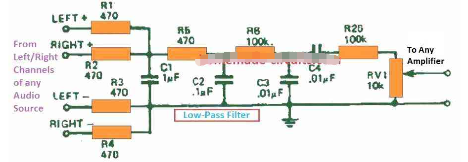

Another option is to implement the above low-pass configuration using a separate speaker system designed specifically for bass reproduction, as described in this article.
Since spare amplifiers can be cumbersome, a simple built-in amplifier like the one used in this project is designed.
Construction
In its mildest form, the booster is used with a separate amplifier. If so, the filter must be made on a small piece of perforated board or tab strip.
The entire unit should be assembled inside a new woofer enclosure (as with our prototype unit) or anywhere else available.
This all-in-one unit can be easily manufactured because most components are fixed directly to the PCB, as shown in Figure 4.
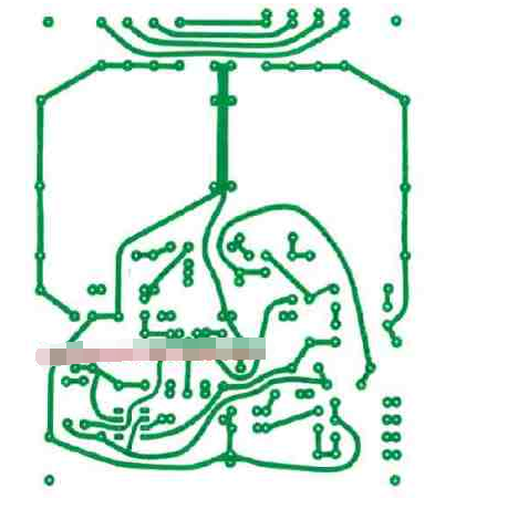
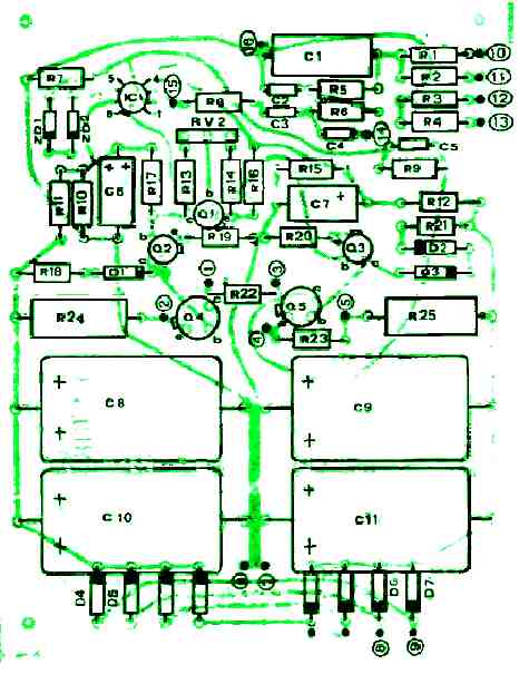
Figure #5
The main power transformer, output transistors and voltage regulator potentiometer are mounted externally.
Then, make connections to the components according to the numbers on the PCB layout and schematic.
Before soldering, you must ensure that all electronic components are placed according to their correct polarity.
Transistors Q6 and Q7 are fixed to the heat sink with insulating washers and connected to pins 1, 2, 3, 4, and 5. The connection points are shown in Figure 2 and Figure 5.
If the amplifier will be placed inside a speaker enclosure, the power transformer must be mounted on rubber.
It is recommended to use shielded cables for connections to the inputs and volume control.
How to Test
Once you are sure all the electronics are in the correct position, set the wiper RV2 in the middle of its travel. Make sure not to connect the speaker at this time.
After that, turn on the 240 V mains supply and measure the voltage at the speaker terminals. It should be below 0.2 V, if it is higher, turn off the power supply and thoroughly check all connections.
If you don't have a multimeter, connect one speaker wire to one side of the amplifier output, then briefly touch the second wire to the other output point.
With a good connection, the speaker should produce no sound or just a faint "click". If the speaker cone jumps out immediately, turn off the power and check the connection again.
If the speakers are silent and everything is working properly, use a milliammeter (if you have one) to measure the current in series with one of the speaker wires.
Fine-tune potentiometer RV2 until the ammeter reads 40 mA. If you don't have a milliammeter, just leave RV2 in the middle position.
Next, connect the leads from your current speakers to the filter inputs and connect the woofer to the booster amplifier.
You can power it up and check the whole system out. Keep in mind that the sound from the bass booster circuit may be a little distorted if you use it from a separate audio source.
However, if you connect the input of the circuit to the terminals of the existing left/right speakers of an existing stereo system, then it may produce incredibly good sound and huge bass levels.
Circuit Description
The complete circuit diagram of the bass enhancement speaker system is shown below
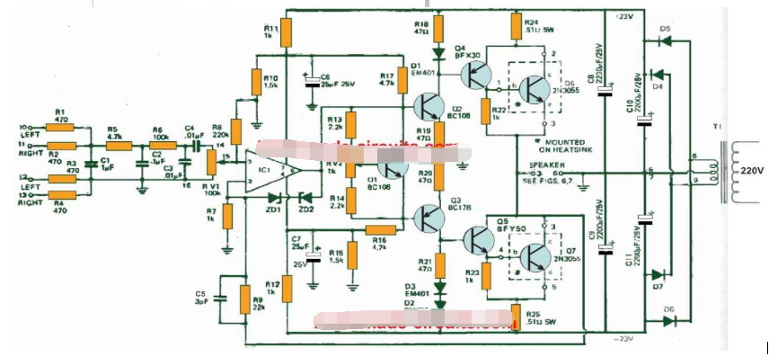
《《Figure #2 Separate high, low, and subwoofer speaker system (Transistors/diodes are not critical, any standard equivalent can be used.)》》
Resistors R1 through R4 combine the outputs of each channel of the current stereo amplifier.
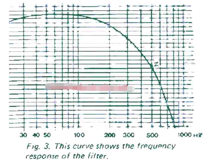
Then, resistors R5, R6 and RV1 and capacitors C1, C2 and C3 create a low-pass filter with a cutoff frequency of approximately 200Hz. In addition, it also has a slope of 18 dB per octave.
To protect the speaker from switching turn-on spikes and transients, capacitor C4 acts as a high-pass filter at approximately 30 Hz.
Figure 1 shows filters for different amplifiers with a 20 dB attenuator connected before the output potentiometer. This prevents overloading of the subsequent amplifier.
Additionally, it outputs about 25 W into 4 ohms and has a frequency response of around 0 Hz to 50 kHz.
However, when an input filter is added, the frequency response of the amplifier becomes identical to that of the filter. Figure 3 shows a plot of the filter response.
The main voltage gain of the amplifier circuit is provided by IC1, Q2, and Q3.
Transistors Q4 and Q5 provide the current gain required to trigger output transistors Q6 and Q7.
Q1 stabilizes Q2 and Q3, and D1 balances transistor Q4. Then, diodes D3 and D4 compensate for transistors Q5 and Q7.
Zener diodes ZD1 and ZD2 protect transistors Q2 and Q3 by limiting the output voltage swing of the IC.
The amplifier discussed in this task can be used without an integrated filter.
This means that the electronics will act as a straight forward 40 W mono amplifier. If this is the case, one of the diodes D2 or D3 or both must be relocated on the heat sink.
Bass Boost Speaker Enclosure
The conditions evaluated for this loudspeaker system are shown in Figures 6 and 7 below.

Figure #6

Figure #7
The chosen speakers for the bass booster circuit are 2 nos 8 ohm Magnavox 20 W models connected in parallel. Therefore the impedance of the speakers is only 4 ohms.
The interior of the speaker housing is covered with absorbent material, such as foam, on the sides, top, and back.
Speaker Wiring Diagram

Parts List
Resistors:

Capacitors:

Semiconductor and others

- How to convert digital values into analog values by connecting MCP4725 with Arduino
- How to Design an Automatic IoT Egg Incubator Using ESP8266
- Homemade CNC plotter
- DIY an indoor and outdoor webcam
- Share a fire sensor solution using MLX90640
- A novel resonance demonstration device
- How to create image processing solutions using HLS capabilities
- Input and output polarity reversal circuit composed of MAX660
- How to use ultrasonic sensors to make a simple nucleic acid sampling machine
- How to Design a Smart Garbage Monitoring System Using IoT
- multi-tone alarm
- "Gong Xi Fa Cai" circuit
- Gas Sensitive Alarm Circuit Part 5
- Gas-sensitive alarm circuit three
- One of the water full alarm circuits
- Equivalent circuit of closed box
- Cheap and good-quality small audio set 01
- Cheap and beautiful bedside HI-FI-03
- Cheap and beautiful bedside HI-FI-01
- Audio/Speaker Data Line Protection Circuit Diagram


 京公网安备 11010802033920号