DIY a simple weather station
Source: InternetPublisher:elleny Keywords: Temperature Sensor Arduino Weather Station Updated: 2024/12/19
This project is a complete DIY weather station that submits its data to the "THINGSPEAK" website, which can be viewed from any browser.
introduce
This project has 4 temperature sensors - 1 outside and 3 in strategic locations. These readings are used to control supplemental heaters when the temperature gets too cold to prevent the pipes from freezing in my old historic house. There is also an ultrasonic distance sensor mounted on the joists to measure the water level if a flood occurs. This project has reignited a long-standing dream of building my own weather station. It has now become quite a complex system with 3 separate microcontrollers communicating and finally sending the data to the internet.
Step 1
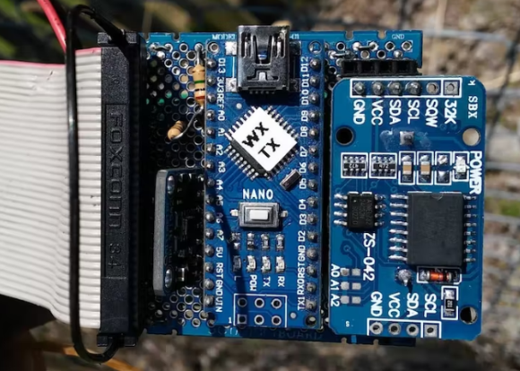
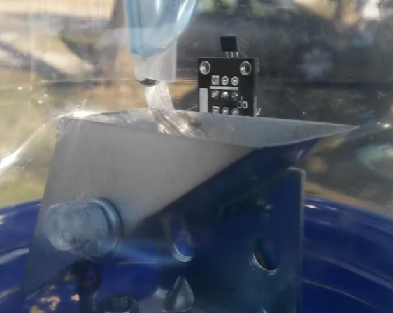
I started with the DHT22 temperature and humidity sensor and Arduino Nano which I already had on hand. I then built a "Tipping Bucket" rain gauge, followed closely by an anemometer. Both the anemometer and rain gauge use Hall Effect sensors and magnets for detection. I also added a barometric pressure module and a real-time clock.
Next, I built a ventilated box to house the DHT and weather station circuitry and mounted everything on a fence about 100 feet from my house. At this stage, all data was only sent to my phone via Bluetooth, so I also added an RF transmitter (433Mhz).


Step 2
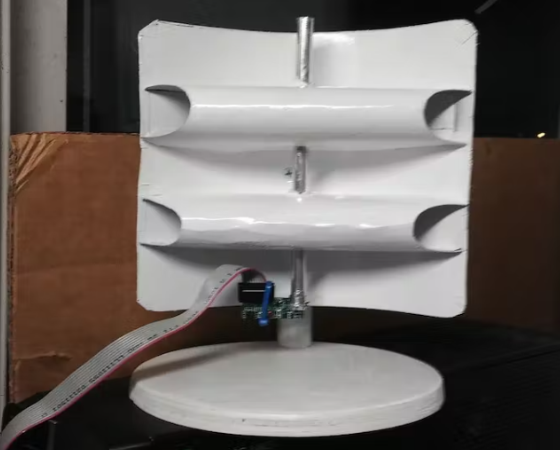
Next I also built the data receiver. I took a superheterodyne RF receiver module, built a parabolic antenna for it, and connected it to an Arduino MEGA type board that I have on my desk, monitoring my "Crawlspace Buddy", and parsing/processing the data.
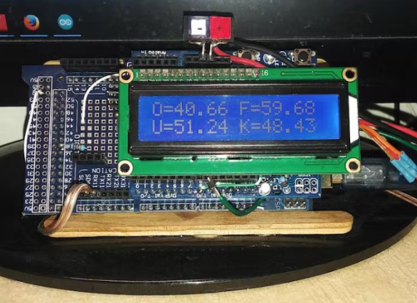
I decided that the MEGA would be the data/control center for several home monitoring projects I had planned. The MEGA is shown in the photo below buried under the MEGA prototype shield, with the LCD mounted on the UNO shield.


Step 3
Finally, I needed to implement the last link in the project chain - connect it to the internet so I could monitor the weather at my house from anywhere in the world. After playing around with the ESP8266 module and breakout board for a few hours, I decided to look for a separate ESP8266-based development board. Based on a few articles I had read, I thought the NodeMCU development board sounded like my best choice, and a search on Amazon revealed a "Weather Station Kit" that included a NodeMCU ESP8266 development board, a DHT11 temperature/humidity sensor, and a .96" OLED display.
It will retrieve weather and forecast data from "Weather Underground", correcting the time from a time server. It will then send the temperature and humidity readings from the DHT to " and add the necessary code to the NodeMCU program. Every 10 minutes, it will receive a summary of the data from MEGA and submit it to the "Thingspeak" website. Here is the link to my public channel which contains my real-time weather data. https://thingspeak.com/channels/463187

Problems to be solved
As is typical of any complex project, there are issues that must be addressed during development. For this project, power for the outdoor station was a major concern. I am currently using 3.7v 18650 type batteries to power the monitoring station. I would eventually like to incorporate solar charging, but this is expected to be a later implementation. For now, I am just monitoring the voltage and replacing the battery when needed.
It turns out that the operating range of these batteries is basically linear, I use 8.4v when fully charged, and the voltage starts to drop at a faster rate when discharged at 7.4v. I use a buck converter to step it down to the system's regulated 5v voltage, which is also connected to the input of the boost regulator through an OptoMOS relay to the output 9.6v to the transmitter. This power supply is only turned on during the actual transmission of a data packet once a minute. (Each packet is sent 2 times to help prevent data loss, as this is only a one-way RF link.)
To maximize battery life, I also implemented sleep/power save, disconnecting the resistors for the LEDs on the Nano, and eliminating the onboard regulator. This brought my power consumption down to about 11 mA in power save mode, 16 mA during normal operation, and about 24 mA during RF transmission. Since both wind speed and rain readings are generated by interrupts, to maintain accuracy of the wind speed measurement, the Nano will only go into power save mode if there have been no input pulses to the anemometer for 10 seconds. With the current setup, I can get about 48-60 hours of use on a set of fully charged batteries before I have to replace them. Wind has a significant impact on potential battery life, so this is a wide range.
in conclusion
This project has taken up about 3 months of my free time and will probably take a bit more to fully implement. I wanted to add a weather vane to monitor wind direction. Another "feature" it has is a set of UV LEDs, though I rarely turn them on due to the high current draw. They shine on the anemometer, which has a cup painted with green fluorescent paint. When it's turned on at night, you'll see a little green ball of light floating back and forth. The idea is to give passersby some help.

- How to convert digital values into analog values by connecting MCP4725 with Arduino
- How to connect TFT LCD to Raspberry Pi
- Homemade CNC plotter
- DIY a simple weather station
- Share a fire sensor solution using MLX90640
- How to Use the Radio to Record Phone Calls Automatically
- Plastic sealing machine circuit diagram
- Electronic Rat Killer Circuit
- How to use ultrasonic sensors to make a simple nucleic acid sampling machine
- Introducing a common reversing radar-----Ultrasonic detector
- Computer host overheating alarm circuit
- SL134 integrated temperature sensor forms a precision Celsius thermometer circuit
- Humidity detection circuit diagram of temperature sensor
- Quartz temperature sensor circuit diagram
- T-X type temperature sensor thermometer
- KTY87 temperature sensor microcontroller interface circuit
- Temperature measurement circuit of KTY81-110 silicon temperature sensor
- AD22100 type temperature sensor circuit with signal conditioning voltage output
- Natural lithium chloride dew point temperature sensor circuit
- Integrated temperature sensor measurement circuit


 京公网安备 11010802033920号