This article introduces the detailed installation and wiring of Siemens PLC, including PLC models: Smart200, S7-300, S7-1200, S7-1500, etc.
Siemens 200 module common PLC wiring diagram
CPU SR20+EMDR32

Siemens S7-300 common module wiring diagram
CPU315+PS307 (power module)+SM321 (DI module)+SM322 (DO module)


Siemens S7-1200 common module wiring diagram
CPU1214C+SM1223

Siemens 1500 common module wiring diagram

The following is a detailed introduction to the S71500 hardware installation and wiring:
Hardware requirements
● 1 × CPU 1511-1 PN (6ES7511-1AK00-0AB0)
●1 S7-1500 load current supply PM 70W 120/230VAC (6EP1332-4BA00)
● 1 mounting rail (6ES7590-1AB60-0AA0)
● 1 digital input module DI 16x24VDC SRC BA (6ES7521-1BH50-0AA0)
● 1 digital output module DQ 16x24VDC/0.5A ST (6ES7522-1BH00-0AB0)
● 2 front connectors (6ES7592-1AM00-0XB0)
● 1 SIMATIC Memory Card with 4 MB (e.g. 6ES7954-8LBxx-0AA0)
● 1 Ethernet cable
Software requirements
● SIMATIC STEP 7 Professional V13 and above
● SIMATIC WinCC Advanced V13 or SIMATIC WinCC Professional V13 and above
Installation assembly steps
1. Install the load current source (PM) on the mounting rail.

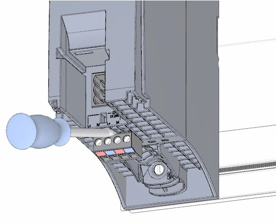
2. Open the front cover and unplug the power connection.

3. Unplug the 4-pin connection plug and tighten the load current supply (PM).

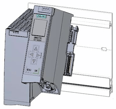
4. Insert the U-shaped connector into the rear of the CPU.

5. Install the CPU on the mounting rail and tighten it.

6. Plug the U-shaped connector into the rear of the digital input module.

7. Attach the digital input module to the mounting rail and screw it tight.

8. Connect the digital output module to the mounting rail and screw it tight.

CPU wiring rules

Steps for wiring the power connection plug
1. Use an appropriate tool to pull out the connector cover.

2. Connect the power cord to the plug according to the wiring diagram. On the other side of the plug, the voltage information that the plug can be used after certification is marked. According to the information on the back of the plug, select the corresponding voltage by inserting the coding element.

3. Close the outer cover.

4. Tighten the screws on the power connection plug.

Wiring the load current supply (PM) to the CPU Steps
1. Wire the 4-pin connector plug of the load current source (PM).

2. Wire the 4-pin connector plug to the 4-pin power connection plug of the CPU.

Wiring steps for digital input modules
1. Insert the front connector into the pre-wiring position. There is no electrical connection between the front connector and the module at the pre-wiring position.

2. Secure the cables with cable ties.

3. Connect the load voltage 24 V DC to terminals 20 (M) and 19 (L+).

4. Insert a potential circuit bridge between the two bottom terminals.

Wiring steps for digital output modules
1. Insert the front connector into the pre-wired location.

2. Supply the DC 24 V supply voltage from terminals 20 (M) and 19 (L+) of the digital input module via terminals 40 (M) and 39 (L+) on the digital input module.

3. Connect four potential circuit bridges.

4. Connect terminals 30 and 40, and 29 and 39.

Steps for wiring the front connector
1. Connect the wires and tighten them according to the wiring diagram inside the terminal cover.

2. To relieve tension, use cable ties to secure the cables and pull tight.

3. Move the front connector from the pre-wiring position to its final position. At this point, the electrical connection between the front connector and the module has been established.

4. Note: The pre-wired front connector can be plugged directly in, e.g. to replace modules.

Steps for starting the CPU for the first time after powering on
1. Plug in the mains connection plug of the load current source (PM).

2. Connect the mains connection plug to the mains.

3. Insert the empty SIMATIC memory card into the CPU

4. Switch the switch on the load power supply (PM) to the RUN position. The CPU starts up.

The CPU starts up and is in STOP mode. Assigning the IP address via the display In this step, you set the IP address and subnet mask of the CPU.
step:
1. Navigate to Settings.
2. Select "Addresses".
3. Select the "X1 (IE/PN)" interface.
4. Select the menu item "IP Addresses".
5. Set the IP address to 192.168.0.10.
6. Press the RIGHT arrow key on the module.
7. Set the subnet mask to 255.255.255.0.
8. Press the "Down" arrow key on the module to select the menu item "Apply" and confirm your settings with "OK".
Siemens PLC wireless communication

Previous article:Classic electrical control principle animation analysis
Next article:How is the accuracy and stability of the linear motor wire cutting machine?
- Popular Resources
- Popular amplifiers
- Red Hat announces definitive agreement to acquire Neural Magic
- 5G network speed is faster than 4G, but the perception is poor! Wu Hequan: 6G standard formulation should focus on user needs
- SEMI report: Global silicon wafer shipments increased by 6% in the third quarter of 2024
- OpenAI calls for a "North American Artificial Intelligence Alliance" to compete with China
- OpenAI is rumored to be launching a new intelligent body that can automatically perform tasks for users
- Arm: Focusing on efficient computing platforms, we work together to build a sustainable future
- AMD to cut 4% of its workforce to gain a stronger position in artificial intelligence chips
- NEC receives new supercomputer orders: Intel CPU + AMD accelerator + Nvidia switch
- RW61X: Wi-Fi 6 tri-band device in a secure i.MX RT MCU
 Professor at Beihang University, dedicated to promoting microcontrollers and embedded systems for over 20 years.
- LED chemical incompatibility test to see which chemicals LEDs can be used with
- Application of ARM9 hardware coprocessor on WinCE embedded motherboard
- What are the key points for selecting rotor flowmeter?
- LM317 high power charger circuit
- A brief analysis of Embest's application and development of embedded medical devices
- Single-phase RC protection circuit
- stm32 PVD programmable voltage monitor
- Introduction and measurement of edge trigger and level trigger of 51 single chip microcomputer
- Improved design of Linux system software shell protection technology
- What to do if the ABB robot protection device stops
- CGD and Qorvo to jointly revolutionize motor control solutions
- CGD and Qorvo to jointly revolutionize motor control solutions
- Keysight Technologies FieldFox handheld analyzer with VDI spread spectrum module to achieve millimeter wave analysis function
- Infineon's PASCO2V15 XENSIV PAS CO2 5V Sensor Now Available at Mouser for Accurate CO2 Level Measurement
- Advanced gameplay, Harting takes your PCB board connection to a new level!
- Advanced gameplay, Harting takes your PCB board connection to a new level!
- A new chapter in Great Wall Motors R&D: solid-state battery technology leads the future
- Naxin Micro provides full-scenario GaN driver IC solutions
- Interpreting Huawei’s new solid-state battery patent, will it challenge CATL in 2030?
- Are pure electric/plug-in hybrid vehicles going crazy? A Chinese company has launched the world's first -40℃ dischargeable hybrid battery that is not afraid of cold
- Application of Lock-in Amplifier in TDLAS Technology
- Addressing the challenges of diverse multi-standard wireless communication devices in the connected home
- [RVB2601 Creative Application Development] Chapter 7: Using lvgl and solving the problem of insufficient SRAM memory
- The difference between polymer tantalum capacitors and ordinary tantalum capacitors
- MSP430FR2355 LaunchPad Development Kit
- PlainDAQ data logger based on Raspberry Pi Pico
- EEWORLD University----Live Replay: Microchip Security Series 21 - Secure Boot and Message Authentication for CAN FD in ADAS and IVI Systems Using TA100-VAO
- FAQ: September 6th TTI&TE "The development and latest application of sensors in industrial motors" live broadcast room Q&A
- 【RT-Thread Software Package Application Works】Photo Album
- Summary of Spectrum Analysis Algorithms

 MCP6141T-E/MS


 京公网安备 11010802033920号