Preface
The current module system of new energy vehicles is composed of many parts, such as batteries, VCU, BSM, motors, etc., but these are relatively mature products. Domestic and foreign module manufacturers have developed many, but there is one module that needs to be paid attention to in the industry, that is, the motor drive part, and the core component of the motor drive part is IGBT (Insulated Gate Bipolar Transistor insulated gate bipolar transistor chip).
01
If you want to understand automotive electronic control IGBT modules from scratch, just read this article!
According to the data from the China Passenger Car Association, the domestic retail penetration rate of new energy vehicles was 27.4% in June 2022, and on June 29, 2022, the European Union announced that the 27 EU member states have reached a preliminary agreement that Europe will ban the sale of fuel vehicles in 2035. The market is becoming more and more prosperous, and at the same time, the newly released new energy vehicle models in China are also flourishing. Whether it is ordinary consumers, practitioners related to the new energy vehicle industry, or investors in the primary and secondary markets, they are gradually paying in-depth attention to some core components of new energy vehicles, especially power device IGBT modules. Today, the editor will talk to you in the form of questions and answers, hoping to help everyone with a more popular explanation.
02
The role of electric drive system and IGBT module
To understand the IGBT module, we must first understand the electric drive system of new energy vehicles. Let's summarize how the electric drive system works in one sentence: When driving a new energy vehicle, the motor controller converts the direct current (DC) released by the power battery into alternating current (AC) (this process is called inversion), which allows the drive motor to work. The motor converts electrical energy into mechanical energy, and then uses the transmission system (mainly the reducer) to make the wheels of the car run. Conversely, the process of converting the mechanical energy of the wheels into storage in the battery is kinetic energy recovery.
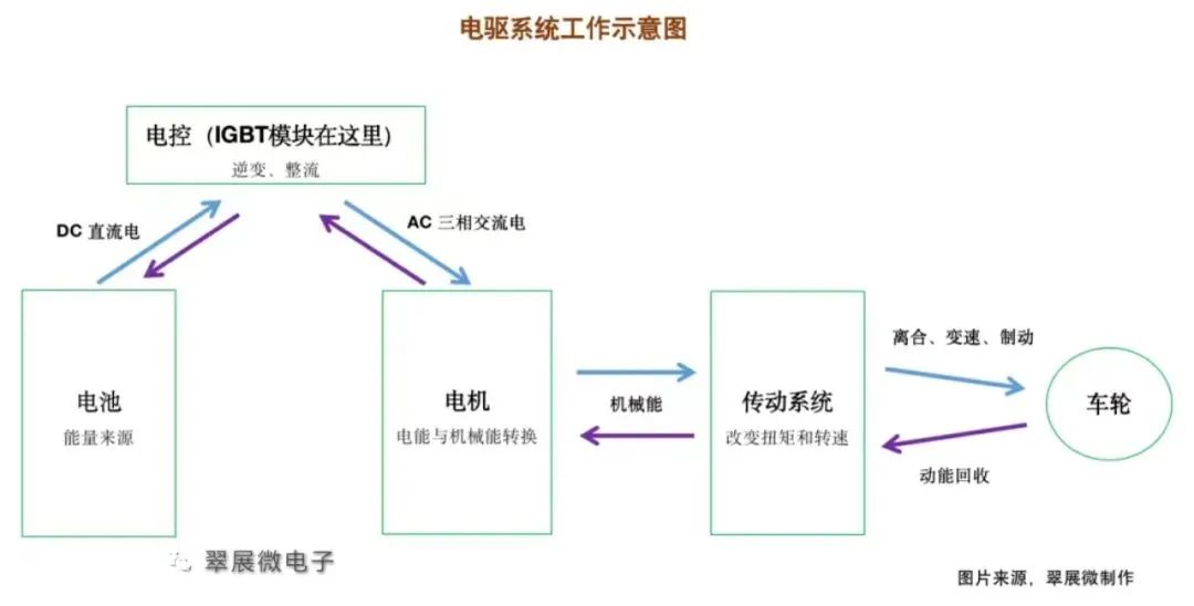
1. What are the “three-electric system” and “electric drive system”?
The three-electric system, namely the power battery (battery for short), drive motor (motor for short), and motor controller (electronic control for short), is also called the three major parts. Together, they account for more than 70% of the total cost of new energy vehicles and are the core components that determine the vehicle's sports performance.
Electric drive system, we generally simply refer to the motor, electronic control, and reducer as the electric drive system.
But strictly speaking, according to Jinjing Electric's prospectus, the electric drive system includes three major assemblies: a drive motor assembly (which converts the electrical energy of the power battery into rotational mechanical energy and is the source of output power), a controller assembly (based on the hardware and software design of power semiconductors, which controls the working status of the drive motor in real time and continuously enriches other control functions), and a transmission assembly (which reduces the output speed and increases the output torque through a gear set to ensure that the electric drive system continues to operate in a high-efficiency range).
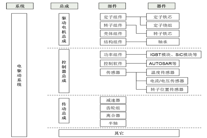
Figure: Schematic diagram of electric drive system
Image source: Jinjing Electric's prospectus
2. What is the “all-in-one electric drive system”?
At first, the motor, electronic control, and reducer were all independent components, but with the advancement of technology, we combined these three parts into one component, which became a "three-in-one electric drive." The purpose of integration is mainly to save space, reduce weight, improve performance, and reduce costs.
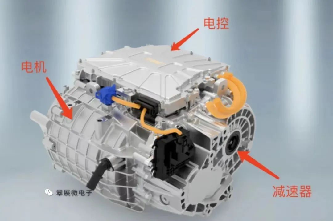
Image source: Juyi Technology official website, Cuizhan Microelectronics
Currently, the most integrated system on the market is the "eight-in-one electric powertrain" of BYD's Fudi Power. This eight-in-one electric drive system integrates the drive motor, motor controller, reducer, on-board charger, DC converter, distribution box, vehicle controller and battery manager.
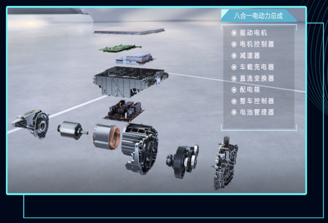
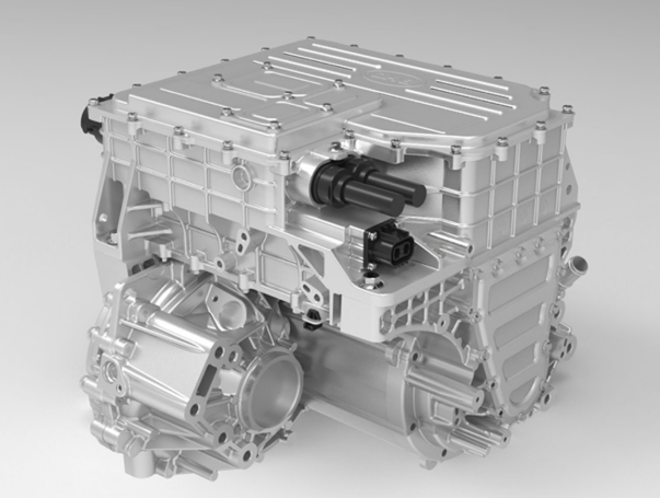
Image source: Fudi Power
Of course, it does not mean that the higher the integration, the better. There are issues that need to be resolved, such as heat dissipation structure design, system stability, and production process maturity. For consumers, the cost of later maintenance is also a big problem. Therefore, how to choose an all-in-one electric drive system requires comprehensive consideration.
3. How does the IGBT module work?
In the electronic control module, the IGBT module is the core component of the inverter. Its working principle is summarized as follows:
Through the semiconductor characteristics of either on or off, without considering the transition process and parasitic effects, we regard a single IGBT chip as an ideal switch. We build a parallel and series structure of several IGBT chip units inside the module. When direct current passes through the module, the outflow direction and frequency of the current are changed by the rapid opening and closing of different switch combinations, so as to output the desired alternating current.
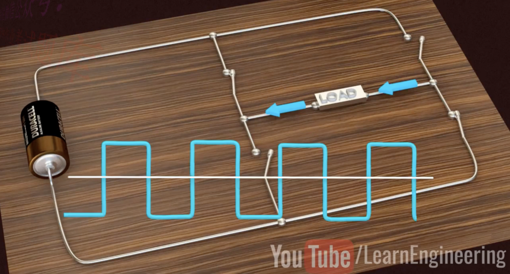
Figure: IGBT inverter principle
The picture is from the Internet, please delete if it infringes
03
IGBT module structure and automotive IGBT module application
The role of the IGBT module in the electric drive system was mentioned above. Now let’s take a closer look at the structure of the IGBT module.
1. What does the IGBT module actually look like?
The standard package of IGBT modules is a flat rectangular block. The following figure shows the top view of the HP1 module. The outermost white part is the plastic shell, and the bottom is a metal base plate (usually copper material) for heat conduction and heat dissipation. You can see that there are many terminals and pins outside the module, each with its own function:
1 is DC positive, 2 is DC negative; 3, 4, 5 are the U, V, W interfaces of three-phase AC power; 6, 25, 22 are the collector signal terminals, 7, 9, 11, 13, 15, 17 are the gate signal terminals; 8, 10, 12, 14, 16, 18 are the emitter signal terminals; 19 is the DC negative signal terminal; 23, 24 are the NTC thermistor terminals.
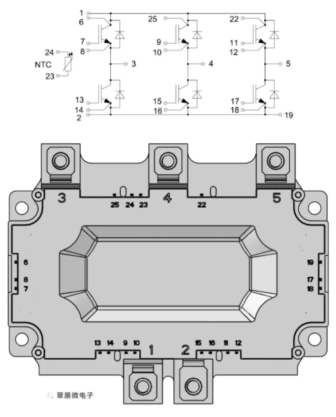
Figure: HP1 module equivalent circuit diagram
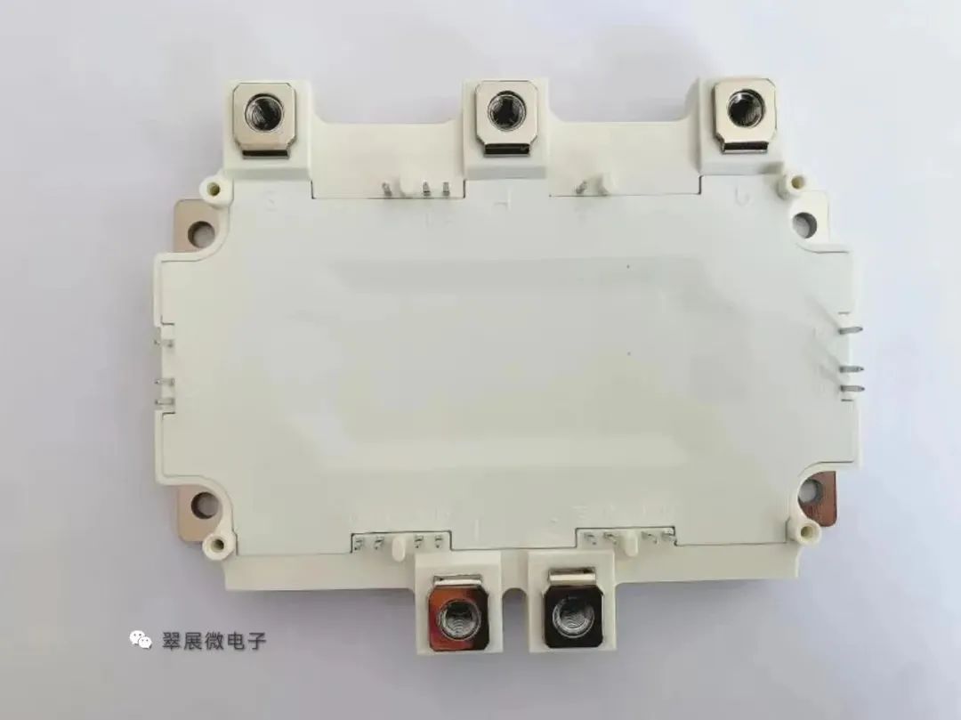
Figure: HP1 module equivalent circuit diagram
Image source: Cuizhanwei
2. What is the basic topology of IGBT?
2023 is already halfway through, and the work of the second quarter has come to an end. In order to further summarize and affirm the work results of the second quarter, we need to face up to and reflect on the current situation.
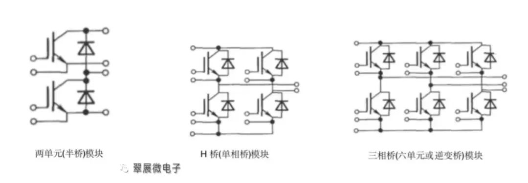
Figure: IGBT module basic circuit topology
Image source: Cuizhanwei
As shown in the figure above, in the IGBT module/single tube, one unit is generally referred to as an IGBT single tube, two units are a single bridge arm (half bridge), four units are H bridges (single-phase bridges), six units are three-phase bridges (full bridges), seven units are generally six units + one braking unit, and eight units are generally six units + a braking unit + a pre-charging unit.
One unit consists of 1, 2 or 3 pairs of FRD+IGBT, of which one pair can be 1 FRD+1 IGBT, or 1 FRD+2 IGBTs, etc.
Please refer to the figure below for the specific object. This is a 6-unit IGBT module.
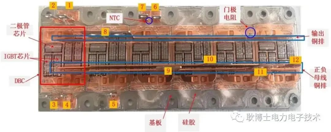
Figure: Infineon Primepack IGBT module
Image source: "Dr. Geng Power Electronics Technology" public account
3. What is the production process of IGBT modules?
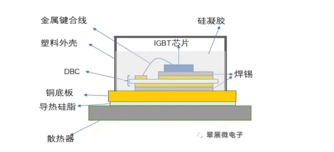
Figure: Cross-section of IGBT standard package structure
Image source: Cuizhanwei
As shown in the figure above, we can see the cross-section interface of the IGBT module. The basic structure of the modules currently using the shell sealing process is not much different. The IGBT module packaging process is roughly as follows:
SMT → vacuum reflow soldering → ultrasonic cleaning → X-ray defect detection → wire bonding → static test → secondary soldering → shell glue filling and curing → terminal forming → functional test (dynamic test, insulation test, reverse bias test)
First, each die on the IGBT wafer is mounted on the DBC. DBC is a copper-clad ceramic substrate, with ceramic in the middle and copper on both sides. DBC plays the role of conductivity and electrical isolation similar to PCB. Commonly used ceramic insulating materials are aluminum oxide (Al2O3) and aluminum nitride (AlN);
Vacuum welding: After mounting, the die and DBC are fixed by vacuum welding. The general solder is tin sheet or solder paste.
X-ray void detection needs to detect bubbles that appear during the bonding process, that is, voids. The presence of voids will seriously affect the thermal resistance and heat dissipation efficiency of the device, resulting in problems such as overheating, burning, and explosion. Generally, automotive IGBT modules require a void rate of less than 1%;
Previous article:Semiconductor Industry Research: One article to help you understand automotive-grade chips
Next article:Microchip CEO: How semiconductors are reshaping the automotive industry
- Popular Resources
- Popular amplifiers
- A new chapter in Great Wall Motors R&D: solid-state battery technology leads the future
- Naxin Micro provides full-scenario GaN driver IC solutions
- Interpreting Huawei’s new solid-state battery patent, will it challenge CATL in 2030?
- Are pure electric/plug-in hybrid vehicles going crazy? A Chinese company has launched the world's first -40℃ dischargeable hybrid battery that is not afraid of cold
- How much do you know about intelligent driving domain control: low-end and mid-end models are accelerating their introduction, with integrated driving and parking solutions accounting for the majority
- Foresight Launches Six Advanced Stereo Sensor Suite to Revolutionize Industrial and Automotive 3D Perception
- OPTIMA launches new ORANGETOP QH6 lithium battery to adapt to extreme temperature conditions
- Allegro MicroSystems Introduces Advanced Magnetic and Inductive Position Sensing Solutions
- TDK launches second generation 6-axis IMU for automotive safety applications
- LED chemical incompatibility test to see which chemicals LEDs can be used with
- Application of ARM9 hardware coprocessor on WinCE embedded motherboard
- What are the key points for selecting rotor flowmeter?
- LM317 high power charger circuit
- A brief analysis of Embest's application and development of embedded medical devices
- Single-phase RC protection circuit
- stm32 PVD programmable voltage monitor
- Introduction and measurement of edge trigger and level trigger of 51 single chip microcomputer
- Improved design of Linux system software shell protection technology
- What to do if the ABB robot protection device stops
- Innovation is not limited to Meizhi, Welling will appear at the 2024 China Home Appliance Technology Conference
- Innovation is not limited to Meizhi, Welling will appear at the 2024 China Home Appliance Technology Conference
- Huawei's Strategic Department Director Gai Gang: The cumulative installed base of open source Euler operating system exceeds 10 million sets
- Download from the Internet--ARM Getting Started Notes
- Learn ARM development(22)
- Learn ARM development(21)
- Learn ARM development(20)
- Learn ARM development(19)
- Learn ARM development(14)
- Learn ARM development(15)
- What does it mean when the port latch is set to 1? How should I understand this sentence? It would be better if there is a picture to illustrate it.
- Simplifying Equalization Design for USB 3.0 Systems
- [2022 Digi-Key Innovation Design Competition] + Smart Cup Holder-01 Unboxing Photos
- MSP430F5529LP's P1.4 port outputs a single PWM wave
- 【MM32 eMiniBoard Review】+ Serial Communication Control of MP3 Player
- Lead and Lag Oscillators
- EEWORLD University Hall----Live playback: IoT display solution using DLP? micro-projection technology
- Recommended development directory for CH579M
- Free gifts! 11 popular Maxim development boards are waiting for you!
- Request: DC-DC small package chip similar to LM2596


 BA6110FS-E1


 京公网安备 11010802033920号