BEGIN: DB HTML The discussion about comparator hysteresis needs to start with the definition of "hysteresis". Like many other technical terms, "hysteresis" comes from the Greek and means "delay" or "lag", or to hinder the change of the previous state. . In engineering, hysteresis is commonly used to describe asymmetric operations. For example, going from A to B and from B to A are different from each other. Hysteresis exists in magnetic phenomena, non-plastic deformation, and comparator circuits.
Most comparators are designed with hysteresis circuits, and the hysteresis voltage is usually 5mV to 10mV. An internal hysteresis circuit prevents the comparator output from oscillating due to parasitic feedback at the input. However, although the internal hysteresis circuit can prevent the comparator from self-oscillation, it is easily overwhelmed by external noise with large amplitude. In this case, external hysteresis needs to be added to improve the anti-interference performance of the system.
First, let's look at the comparator's transfer characteristics.
Figure 1 shows the transfer characteristics of an ideal comparator without internal hysteresis circuit, and
Figure 2 shows the transfer characteristics of an actual comparator. As can be seen from Figure 2, the actual voltage comparator output does not start to change until the input voltage (V IN ) increases to 2mV.
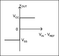
Figure 1. Transfer characteristics of an ideal comparator
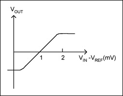
Figure 2. Actual comparator transfer characteristics
The operational amplifier can be used as a comparator in the open loop state, but once there is a small amount of noise or interference in the input signal, it will produce undesirable frequent transitions between two different output states (Figure 3 ). Replacing the open-loop op amp with a comparator with internal hysteresis suppresses frequent transitions and oscillations in the output. Or add an external hysteresis circuit to the positive feedback circuit of the comparator. The function of positive feedback is to ensure that the output changes rapidly from one state to another, so that the fuzzy state time of the comparator's output reaches a negligible level. If Adding a hysteresis circuit to the positive feedback can slow down this frequent jump.

Figure 3. Fuzzy state and frequent transitions of comparator output without hysteresis circuit
As an example, consider the simple circuit shown in Figure 4 , with the transmission characteristics shown in Figure 5. The inverting input voltage of the comparator changes linearly from 0, and the voltage dividing resistors R1 and R2 form positive feedback. When the input voltage increases from point 1 ( Figure 6 ), the output will remain at V CC until the input voltage exceeds the non-inverting threshold V TH+ = V CC R2/(R1 + R2) . At the threshold point, the output voltage quickly jumps from V CC to V SS because the input voltage at the inverting terminal is greater than the input voltage at the non-inverting terminal. The output remains low until the input passes the new threshold point 5, V TH- = V SS R2/(R1 + R2). At 5 o'clock, the output voltage quickly jumps back to V CC because the non-inverting input voltage is now higher than the inverting input voltage.
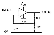
Figure 4. Simple circuit with hysteresis

Figure 5. Transmission characteristics of the circuit of Figure 4
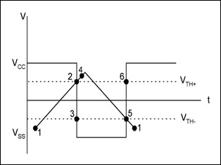
Figure 6. Input/output voltage waveforms for the circuit of Figure 4
The corresponding relationship between the output voltage V OUT and the input voltage V IN in the circuit shown in Figure 4 shows that the output voltage will not change until the input voltage changes by at least 2V TH . Therefore, it is different from the response case of Figure 3 (the amplifier has no hysteresis), that is, any noise or interference less than 2V TH will not cause a rapid change in the output. In practical applications, the thresholds of positive and negative voltages can be set by selecting an appropriate feedback network.
Other settings can be obtained by adding hysteresis circuits with different threshold voltages.
The circuit in Figure 7 uses two MOSFETs and a resistor network to adjust the thresholds for positive and negative polarity. Unlike the comparator shown in Figure 4, the resistive feedback network is not loaded into the load loop.
Figure 8 shows the output response when the input signal changes.
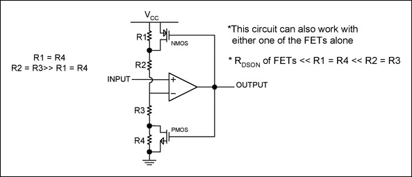
Figure 7. Hysteresis circuit formed by external MOSFET and resistor

Figure 8. Input/output voltage waveforms for the circuit of Figure 7
Different output configurations within the comparator require different external hysteresis circuits. For example, a comparator with an internal pull-up resistor can add positive feedback resistors directly to the output and non-inverting input. The input voltage divider network acts on the non-inverting input terminal of the comparator, and the inverting input voltage is a fixed reference level (as shown in Figure 9 ).

Figure 9. Adding hysteresis circuit to comparator with pull-up resistor
As mentioned above, a comparator with internal hysteresis provides two thresholds: one for detecting the input rising voltage (V THR ) and one for detecting the input falling voltage (V THF ), corresponding to V TH1 and V TH2 in Figure 8 . The difference between the two thresholds is the hysteresis band (V HB ). When the comparator input voltages are equal, the hysteresis circuit causes one input to quickly cross over the other, thus allowing the comparator to avoid the region where oscillation occurs.
Figure 10 shows the working process when the voltage at the inverting input terminal of the comparator is fixed and the voltage at the non-inverting input terminal changes. Similar waveforms can be obtained by exchanging the two inputs, but the polarity of the output voltage is opposite.

Figure 10. Input/output voltage waveforms for the circuit of Figure 9
The resistor values of the feedback divider network can be easily calculated based on the two extreme values of the output voltage (two supply swings).
There are internal comparators with 4mV hysteresis and a pull-up resistor at the output - such as Maxim's MAX9015, MAX9017 and MAX9019. These comparators are designed for single-supply systems with voltage swings between V CC and 0V. You can follow the steps below to select and calculate the required components based on the given supply voltage, voltage hysteresis (V HB ) and reference voltage (V REF ):
Step 1:
Select R3. The current flowing through R3 at the trigger point is (V REF - V OUT )/R3. Considering the two possible states of the output, R3 is obtained by the following two equations:
R3 = V REF /IR3 and R3 = (V CC - V REF )/IR3.
Take the smaller resistance value in the calculation result, for example, V CC = 5V, IR3 = 0.2μA, using the MAX9117 comparator (V REF = 1.24V), the calculated results are 6.2M  and 19M
  , and R3 is selected to be 6.2M
  .
.
Step 2
Select the hysteresis voltage (V HB ). In this example, the hysteresis voltage is selected to be 50mV.![]()
Step 3
R1 can be calculated according to the following formula.
For this example, the value of R1 is:
Step 4 Enter the selection of
V IN rising threshold (V THR![]()
). For example: at this threshold point, when the input voltage V IN exceeds the threshold, the comparator output changes from low level to high level. In this example, select V THR = 3V.
Step 5:
Calculate R2. R2 can be calculated as follows: ![]()
In this example, the standard value of R2 is 44.2k  .
.
Step 6
Verify the voltage and hysteresis voltage as follows: V IN rising threshold = 2.992V, which is equal to V REF times R1, divided by the resistance of R1, R2, and R3 in parallel. 
V IN falling threshold = 2.942V. Therefore, hysteresis voltage = V THR - V THF = 50mV.
Finally, the internal hysteresis voltage of the open-drain structure comparator is 4mV (MAX9016, MAX9018, MAX9020), and an external pull-up resistor is required, as shown in Figure 11. Added hysteresis can be generated through positive feedback, but the calculation formula is slightly different from that of the pull-up output. Hysteresis voltage = V THR - V THF = 50mV. Calculate the resistance value as follows:
Step 1:
Select R3. The leakage current at the IN_+ terminal is less than 2nA, so the current through R3 is at least 0.2μA to reduce the error caused by leakage current. R3 can be obtained from R3 = V REF /IR3 or R3 = [(V CC - V REF )/IR3] - R4, whichever is smaller. For example, using MAX9118 (V REF =1.24V), V CC = 5V, IR3 = 0.2μA, R4 = 1M  , the calculation results are 6.2M
  and 18M
  , then select 6.2M for R3
  .
.
Step 2
Select the desired hysteresis voltage (V HB ).
Step 3
Select R1. R1 can be calculated as follows: ![]()
In this example, R1 is:![]()
Step 4
Select the V IN rising threshold (V THR ) as follows: ![]()
At this threshold point, when the input voltage V IN exceeds the threshold, the comparator output changes from low level to high level. In this example, select V THR = 3V.
Step 5
Calculate R2 as follows: 
In this example, the standard value of R2 is 49.9k  .
.
Step 6
: Verify the trigger voltage and hysteresis voltage as follows:

Figure 11. Adding a hysteresis circuit to a comparator whose output is an open-drain structure
Previous article:Op amps that can sink and source current
Next article:Establishing the external hysteresis voltage for the comparator
Recommended ReadingLatest update time:2024-11-17 06:02

- Popular Resources
- Popular amplifiers
- High signal-to-noise ratio MEMS microphone drives artificial intelligence interaction
- Advantages of using a differential-to-single-ended RF amplifier in a transmit signal chain design
- ON Semiconductor CEO Appears at Munich Electronica Show and Launches Treo Platform
- ON Semiconductor Launches Industry-Leading Analog and Mixed-Signal Platform
- Analog Devices ADAQ7767-1 μModule DAQ Solution for Rapid Development of Precision Data Acquisition Systems Now Available at Mouser
- Domestic high-precision, high-speed ADC chips are on the rise
- Microcontrollers that combine Hi-Fi, intelligence and USB multi-channel features – ushering in a new era of digital audio
- Using capacitive PGA, Naxin Micro launches high-precision multi-channel 24/16-bit Δ-Σ ADC
- Fully Differential Amplifier Provides High Voltage, Low Noise Signals for Precision Data Acquisition Signal Chain
- Innolux's intelligent steer-by-wire solution makes cars smarter and safer
- 8051 MCU - Parity Check
- How to efficiently balance the sensitivity of tactile sensing interfaces
- What should I do if the servo motor shakes? What causes the servo motor to shake quickly?
- 【Brushless Motor】Analysis of three-phase BLDC motor and sharing of two popular development boards
- Midea Industrial Technology's subsidiaries Clou Electronics and Hekang New Energy jointly appeared at the Munich Battery Energy Storage Exhibition and Solar Energy Exhibition
- Guoxin Sichen | Application of ferroelectric memory PB85RS2MC in power battery management, with a capacity of 2M
- Analysis of common faults of frequency converter
- In a head-on competition with Qualcomm, what kind of cockpit products has Intel come up with?
- Dalian Rongke's all-vanadium liquid flow battery energy storage equipment industrialization project has entered the sprint stage before production
- Allegro MicroSystems Introduces Advanced Magnetic and Inductive Position Sensing Solutions at Electronica 2024
- Car key in the left hand, liveness detection radar in the right hand, UWB is imperative for cars!
- After a decade of rapid development, domestic CIS has entered the market
- Aegis Dagger Battery + Thor EM-i Super Hybrid, Geely New Energy has thrown out two "king bombs"
- A brief discussion on functional safety - fault, error, and failure
- In the smart car 2.0 cycle, these core industry chains are facing major opportunities!
- Rambus Launches Industry's First HBM 4 Controller IP: What Are the Technical Details Behind It?
- The United States and Japan are developing new batteries. CATL faces challenges? How should China's new energy battery industry respond?
- Murata launches high-precision 6-axis inertial sensor for automobiles
- Ford patents pre-charge alarm to help save costs and respond to emergencies
- The significance of choosing high current spring micro-needle module for mobile phone connector testing
- Using debug macro definition to turn on/off debug output in C/C++
- [ACM32F070 supporting capacitive touch development board target -- Arduino preparation for dual-machine UART communication linkage]
- Automotive digital diagnostic tool box
- Award-winning live broadcast: ADI digital active noise reduction headphone solution invites you to listen on August 6th to let technology calm us down
- FOC dual motor development board
- Answer questions to win prizes | ADI Technology Express Issue 1
- Capacitance and inductance recording
- After 12 days, he was taken to quarantine
- What is the prospect of the development of artificial intelligence?

 A low-latency and low-power PWM comparator circuit design


 京公网安备 11010802033920号