1. Introduction
HART, which stands for Highway Addressable Remote Transducer, is the abbreviation of Highway of Addressable Remote Sensors. It was first developed by Rosemount Corporation in the United States and supported by more than 80 well-known instrument companies. Its characteristic is that it allows two-way digital communication without interfering with 4-20mA analog signals.
Intelligent electromagnetic flowmeters that comply with the HART protocol can not only detect and display various flow rates locally, but can also be remotely set through the host meter to change the zero point and range of the flowmeter, as well as complete self-diagnosis and other functions, which greatly facilitates the use and maintenance of the flowmeter, and thus has strong market competitiveness. [1] This paper discusses the technical issues of the specific implementation of intelligent electromagnetic flowmeters based on the HART protocol. First, it is necessary to solve the design problem of the hardware circuit, and second, it is necessary to discuss the implementation of HART protocol command set programming and the implementation of host computer software.
2 Introduction to HART Protocol
The HART protocol follows the OSI open system interconnection reference model developed by ISO and uses the first, second and seventh layers of the OSI model, namely the physical layer, data link layer and application layer.
2.1 Physical layer specifications
The HART protocol uses the Bell 202 frequency shift keying (FSK) standard of the American telephone communication system, with a ±0.5 mA sine wave at 4-20 mA and a baud rate of 1200 bps. Because the average value of the superimposed sine signal is 0, and the phase-continuous frequency shift keying technology requires that the phase angle at the boundary of the data bit 1 and 0 at a baud rate of 1200 Hz is continuous, the digital communication signal will not affect the 4-20 mA analog signal.
2.2 Data Link Layer Specification [2][3]
This part of the protocol specifies the format of the HART frame to achieve the establishment, maintenance, and data link communication functions. The HART protocol uses redundant error detection code information, an error detection mechanism, and the automatic repeat request protocol (ARQ) to achieve error-free transmission of communication data.
The data transmission related to the protocol is realized in the form of frames. The frame is the encapsulation of user control and addressing information to user data. The frame can only be identified after the byte counting in the frame is completed and the error check is received correctly or the physical layer notifies the signal transmission to terminate (such as the carrier cannot be detected). The format of the HART frame is shown in Figure 1.

PREAMBLE Preamble signal.
DELIM Delimiter: a unique or most easily recognizable character.
ADDR Address byte: contains the source address and destination address, and the highest bit is used to indicate the address of the master device associated with the frame.
COM Command byte: indicates the function to be performed by the field instrument.
BYTE CORNT Total data length: This value indicates the number of bytes from the next byte of BYTE CORNT to the end (excluding the check byte).
DATA Data byte.
CHK Parity check: longitudinal parity check.
The HART protocol in the data link layer is a "master/slave" protocol. In addition to the confirmation command that has been received in the response message of the slave device, many messages also contain the data inquired by the master device. The HART protocol allows two master devices to run in the system at the same time, a basic master device and a secondary master device. The slave device distributes its own response command message to the two master devices according to their different addresses.
2.3 Application layer specification [4]
specifies three types of commands in the HART message packet. The first type is general commands, which are applicable to all products that comply with the HART protocol and provide functional descriptions for devices that comply with the HART protocol. The second type is general operation commands, which are applicable to most products that comply with the HART protocol. The third type is device-specific commands, which are applicable to special products that comply with the HART protocol.
3 Hardware design of intelligent electromagnetic flowmeter based on HART protocol
The hardware system circuit of the intelligent electromagnetic flowmeter with HART communication protocol adopts modular design, mainly including sensor module, MCU module, HART communication module and human-machine interface module.
The low-frequency excitation current controlled by the single-chip microcomputer is output to the excitation coil of the sensor. At the same time, the tiny potential signal from the electromagnetic flow sensor is sent to the single-chip microcomputer through the AD analog-to-digital conversion circuit after preamplification. The single-chip microcomputer collects data on these signals, analyzes and processes them, and sends them to the LCD screen for instantaneous flow and cumulative flow display. At the same time, the single-chip microcomputer compensates the obtained flow value through the calculation formula, and the compensated flow signal is used to realize remote communication with the host computer through the HART communication module.
3.1 Design of HART communication module
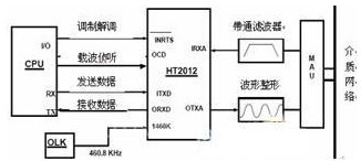
The HT2012 chip is used to implement the demodulation and modulation process of the communication signal in the HART protocol. Figure 2 shows the connection between the modem and the microprocessor.
The demodulation process of the HART signal: After the pulse signal output by the bandpass filter enters the HT2012, the modem demodulates the 1200Hz and 2200Hz in the pulse signal into digital 1 and 0 respectively, and then outputs the digital signal from the ORXD port of the HT2012. The CPU judges the received data and executes the corresponding tasks.

3.2 HT2012 and external interface
The HART digital signal specification is a sinusoidal AC current signal with a peak value of 1mA and an average value of 0mA. This signal is converted into a sinusoidal AC voltage signal through line impedance, while the HT2012 input and output signals are 0-5V square wave signals. Therefore, a filtering circuit and a shaping circuit are required between the HT2012 and the external HART signal.
As shown in Figure 3, the filter composed of TLC27 is a bandpass filter, which is used to reduce the noise interference of the received signal. The filter is also used to eliminate the peaks in the waveform, so that the received signal becomes smooth. The digital square wave generation circuit composed of TLC37 converts the sine wave filtered by TLC27 into a corresponding square wave for HT2012 reception.

As shown in Figure 4, the role of the buffer 74HC126 is to make the rising and falling edges of the square wave smooth, so that the signal meets the rising and falling edge timing requirements of the signal waveform required by the HART physical layer specification, because the smoother rising and falling edge times can reduce crosstalk with other networks.
HT2012 requires an external 460.8kHz clock signal, and the error of the clock frequency is required to be ±0.1%. If a 460.8kHz crystal oscillator is directly input, it will not only increase the power consumption of the system, but also the crystal oscillator is a non-standard crystal oscillator and needs to be specially customized. In order to solve this problem, a 1.8432MHz crystal oscillator is used in the system to generate a clock signal, and then divided by 4 by the frequency divider CD4013, it can output a divided frequency signal of 1.8432MHz/4=460.8kHz for HT2012.
The internal voltage regulator of AD421 and the external field effect tube DN25D adjust the voltage input to AD421, and can provide +3.3V voltage as the power supply for other devices. The FSK signal sent by HART is sent to AD421 through a capacitor coupling, converted into the corresponding ±0.5mA sinusoidal current signal, realizing the conversion of voltage signal to current signal. At the same time, it is superimposed on the 4~20mA current and sent to the receiving device, realizing the exchange of information of HART protocol. The coupling capacitor of this circuit is 0.0033μF.
4 Software Implementation of HART Communication Protocol
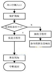
4.1 Serial Port Interrupt Program of Intelligent Electromagnetic Flowmeter [5]
In the serial port interrupt service program, the scene is first protected, and then it is determined whether it is a receiving interrupt or a sending interrupt. If it is a receiving interrupt, the receiving service subroutine is executed, otherwise the sending service subroutine is executed. After the interrupt processing is completed, the scene is restored and the system main program is returned. HART communication uses horizontal and vertical verification methods. When an error is detected in the received data, the master device is notified of the data reception error after the master device command frame is sent. The master device resends the command frame to ensure accurate and reliable communication. The flow chart of the HART serial port interrupt subroutine is shown in Figure 5.

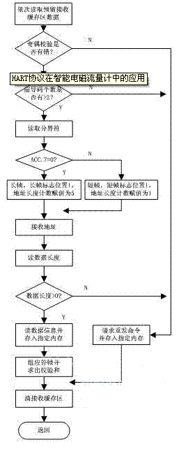
4.2 HART command splitting subroutine [6][7]
Before responding to the command frame, the frame must be split. That is, first determine whether the preamble of the frame is correct. Each time a preamble is received, the counter is increased by 1. Then receive the delimiter. If it is a valid delimiter and the preamble counter is greater than 1, it is the starting position of the HART frame. The type of HART frame is determined according to the delimiter. If it is a response frame or a burst mode frame, the receiving service is terminated and the carrier is waited for to end. If it is a request frame, the frame format is determined and the address count value of the long frame format or short frame format is set. The short frame format address receives 1 byte and the long frame format address receives 5 bytes. Then receive the command number and the data byte length byte. If the data byte length byte has a parity error, the receiving service is terminated and the carrier is waited for to end. Otherwise, the data byte length counter is set. Each time a data byte is received, the length counter is reduced by 1. Finally, the horizontal checksum is received. If the receiving request address matches, the horizontal checksum of the received HART frame is XORed and compared with the received horizontal checksum. If they are the same, it means there is no communication error. Otherwise, the horizontal checksum error flag is set to 1, the receiving service is terminated and the HART command execution subroutine is entered. The command frame splitting program flow is shown in Figure 6.

5 Conclusions The
test results of the developed intelligent electromagnetic flowmeter show that: the flowmeter has high integration, powerful functions, convenient operation and reliable performance; it has self-diagnosis, self-testing and HART data communication functions; it can measure the flow in both the forward and reverse directions, and also the pulsating flow; it has good anti-electromagnetic interference and temperature performance, and is suitable for on-site measurement and display; it has a large measurement range and high accuracy.
Previous article:Principle and Design of New CMOS Image Sensor
Next article:Pulse detection method of human bioelectrical impedance and its application
Recommended ReadingLatest update time:2024-11-16 22:56


- Popular Resources
- Popular amplifiers
- High signal-to-noise ratio MEMS microphone drives artificial intelligence interaction
- Advantages of using a differential-to-single-ended RF amplifier in a transmit signal chain design
- ON Semiconductor CEO Appears at Munich Electronica Show and Launches Treo Platform
- ON Semiconductor Launches Industry-Leading Analog and Mixed-Signal Platform
- Analog Devices ADAQ7767-1 μModule DAQ Solution for Rapid Development of Precision Data Acquisition Systems Now Available at Mouser
- Domestic high-precision, high-speed ADC chips are on the rise
- Microcontrollers that combine Hi-Fi, intelligence and USB multi-channel features – ushering in a new era of digital audio
- Using capacitive PGA, Naxin Micro launches high-precision multi-channel 24/16-bit Δ-Σ ADC
- Fully Differential Amplifier Provides High Voltage, Low Noise Signals for Precision Data Acquisition Signal Chain
- Innolux's intelligent steer-by-wire solution makes cars smarter and safer
- 8051 MCU - Parity Check
- How to efficiently balance the sensitivity of tactile sensing interfaces
- What should I do if the servo motor shakes? What causes the servo motor to shake quickly?
- 【Brushless Motor】Analysis of three-phase BLDC motor and sharing of two popular development boards
- Midea Industrial Technology's subsidiaries Clou Electronics and Hekang New Energy jointly appeared at the Munich Battery Energy Storage Exhibition and Solar Energy Exhibition
- Guoxin Sichen | Application of ferroelectric memory PB85RS2MC in power battery management, with a capacity of 2M
- Analysis of common faults of frequency converter
- In a head-on competition with Qualcomm, what kind of cockpit products has Intel come up with?
- Dalian Rongke's all-vanadium liquid flow battery energy storage equipment industrialization project has entered the sprint stage before production
- Allegro MicroSystems Introduces Advanced Magnetic and Inductive Position Sensing Solutions at Electronica 2024
- Car key in the left hand, liveness detection radar in the right hand, UWB is imperative for cars!
- After a decade of rapid development, domestic CIS has entered the market
- Aegis Dagger Battery + Thor EM-i Super Hybrid, Geely New Energy has thrown out two "king bombs"
- A brief discussion on functional safety - fault, error, and failure
- In the smart car 2.0 cycle, these core industry chains are facing major opportunities!
- The United States and Japan are developing new batteries. CATL faces challenges? How should China's new energy battery industry respond?
- Murata launches high-precision 6-axis inertial sensor for automobiles
- Ford patents pre-charge alarm to help save costs and respond to emergencies
- New real-time microcontroller system from Texas Instruments enables smarter processing in automotive and industrial applications
- Some matters needing attention in the design of multi-channel output switching power supply
- In a single-chip computer, writing 1 clears it to 0, and writing 0 clears it to 0. What is the difference?
- 【Help】Sensor selection for a certain op amp circuit
- DIY thermal imaging is convenient for observing frictional heat generation
- RP2040 components purchased from element14 event
- Flushing steps (smart toilet development record)
- How to speed up MobaXterm pasting
- Award-winning live broadcast | The new Infineon MOSFET based on Source-down technology effectively improves power density, which is visible to the naked eye
- Bike modification series: Modification buttons
- Hot Questions and Answers: What else can you do besides IT?

 Learn to repair variable frequency air conditioner easily with zero basic knowledge (Zhang Yunkun and Zhang Xinde)


 京公网安备 11010802033920号