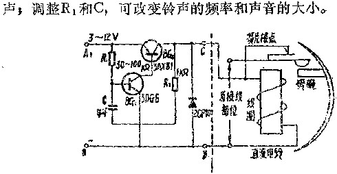
The DC bell is equipped with an electronic contact circuit to replace the original reed contact, which can avoid the failure of the bell to ring due to improper adjustment of the reed contact and rust.
The electronic contact circuit is an oscillating circuit composed of two triodes. After the circuit oscillates, a pulse current with a frequency of 100HZ is input to the bell coil, causing the bell to ring.

Previous article:Digital display "mother and child clock" circuit diagram
Next article:Circuit diagram of simple automatic bell ringing device
- Popular Resources
- Popular amplifiers
- High signal-to-noise ratio MEMS microphone drives artificial intelligence interaction
- Advantages of using a differential-to-single-ended RF amplifier in a transmit signal chain design
- ON Semiconductor CEO Appears at Munich Electronica Show and Launches Treo Platform
- ON Semiconductor Launches Industry-Leading Analog and Mixed-Signal Platform
- Analog Devices ADAQ7767-1 μModule DAQ Solution for Rapid Development of Precision Data Acquisition Systems Now Available at Mouser
- Domestic high-precision, high-speed ADC chips are on the rise
- Microcontrollers that combine Hi-Fi, intelligence and USB multi-channel features – ushering in a new era of digital audio
- Using capacitive PGA, Naxin Micro launches high-precision multi-channel 24/16-bit Δ-Σ ADC
- Fully Differential Amplifier Provides High Voltage, Low Noise Signals for Precision Data Acquisition Signal Chain
- LED chemical incompatibility test to see which chemicals LEDs can be used with
- Application of ARM9 hardware coprocessor on WinCE embedded motherboard
- What are the key points for selecting rotor flowmeter?
- LM317 high power charger circuit
- A brief analysis of Embest's application and development of embedded medical devices
- Single-phase RC protection circuit
- stm32 PVD programmable voltage monitor
- Introduction and measurement of edge trigger and level trigger of 51 single chip microcomputer
- Improved design of Linux system software shell protection technology
- What to do if the ABB robot protection device stops
- Learn ARM development(19)
- Learn ARM development(14)
- Learn ARM development(15)
- Analysis of the application of several common contact parts in high-voltage connectors of new energy vehicles
- Wiring harness durability test and contact voltage drop test method
- From probes to power supplies, Tektronix is leading the way in comprehensive innovation in power electronics testing
- From probes to power supplies, Tektronix is leading the way in comprehensive innovation in power electronics testing
- Sn-doped CuO nanostructure-based ethanol gas sensor for real-time drunk driving detection in vehicles
- Design considerations for automotive battery wiring harness
- Do you know all the various motors commonly used in automotive electronics?
- Analysis of the working principles of seven triode collector DC circuits 5
- About the Wireless Charging Electric Car for the Undergraduate Group of the 2018 College Electronics Competition
- Are electronic engineers' desks always messy? Let's talk about it
- Share Altium_Designer_Beta_19.1.5
- Why is the voltage ringing spike of MOSFET different in boost and buck mode?
- The circuit for discharging the PFC output capacitor is shown in Figure 2.
- Basic syntax of Verilog HDL
- Found a method to import Altium Designer into SIwave
- Thanks to okhxyyo for searching and fish001 for sharing
- Please advise, is it easy to pass the postgraduate examination and graduate, and how useful is the degree certificate?

 MM74C909N/B+


 京公网安备 11010802033920号