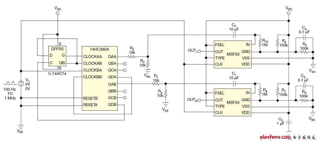
The circuit uses the MSFS5 selectable low-pass/bandpass switched capacitor filter to eliminate the harmonics of a square wave applied to its input. The clock of the MSFS5 is 100 times the input square wave. The 74HC390 and 74HC74 form a 25-divide and 2-divide circuit. The Q output of the 74HC74 is connected to the two 2-divide circuits of the 74HC390A, and the square wave frequency generated is 1/100 of the filter clock frequency, and the phase difference is 90°. The square wave of the CMOS level will saturate the filter, so the circuit uses a resistor divider composed of R1 to R4 to reduce the amplitude of the signal. The circuit in the figure can obtain a swept sine/cosine pair in the frequency range of 1 Hz to 25 kHz (click to enlarge).

Previous article:Simple RF Test Oscillator Circuit
Next article:Inverter pulse counter circuit
- Popular Resources
- Popular amplifiers
- High signal-to-noise ratio MEMS microphone drives artificial intelligence interaction
- Advantages of using a differential-to-single-ended RF amplifier in a transmit signal chain design
- ON Semiconductor CEO Appears at Munich Electronica Show and Launches Treo Platform
- ON Semiconductor Launches Industry-Leading Analog and Mixed-Signal Platform
- Analog Devices ADAQ7767-1 μModule DAQ Solution for Rapid Development of Precision Data Acquisition Systems Now Available at Mouser
- Domestic high-precision, high-speed ADC chips are on the rise
- Microcontrollers that combine Hi-Fi, intelligence and USB multi-channel features – ushering in a new era of digital audio
- Using capacitive PGA, Naxin Micro launches high-precision multi-channel 24/16-bit Δ-Σ ADC
- Fully Differential Amplifier Provides High Voltage, Low Noise Signals for Precision Data Acquisition Signal Chain
- Innolux's intelligent steer-by-wire solution makes cars smarter and safer
- 8051 MCU - Parity Check
- How to efficiently balance the sensitivity of tactile sensing interfaces
- What should I do if the servo motor shakes? What causes the servo motor to shake quickly?
- 【Brushless Motor】Analysis of three-phase BLDC motor and sharing of two popular development boards
- Midea Industrial Technology's subsidiaries Clou Electronics and Hekang New Energy jointly appeared at the Munich Battery Energy Storage Exhibition and Solar Energy Exhibition
- Guoxin Sichen | Application of ferroelectric memory PB85RS2MC in power battery management, with a capacity of 2M
- Analysis of common faults of frequency converter
- In a head-on competition with Qualcomm, what kind of cockpit products has Intel come up with?
- Dalian Rongke's all-vanadium liquid flow battery energy storage equipment industrialization project has entered the sprint stage before production
- Allegro MicroSystems Introduces Advanced Magnetic and Inductive Position Sensing Solutions at Electronica 2024
- Car key in the left hand, liveness detection radar in the right hand, UWB is imperative for cars!
- After a decade of rapid development, domestic CIS has entered the market
- Aegis Dagger Battery + Thor EM-i Super Hybrid, Geely New Energy has thrown out two "king bombs"
- A brief discussion on functional safety - fault, error, and failure
- In the smart car 2.0 cycle, these core industry chains are facing major opportunities!
- The United States and Japan are developing new batteries. CATL faces challenges? How should China's new energy battery industry respond?
- Murata launches high-precision 6-axis inertial sensor for automobiles
- Ford patents pre-charge alarm to help save costs and respond to emergencies
- New real-time microcontroller system from Texas Instruments enables smarter processing in automotive and industrial applications
- [TI mmWave Radar Review] + Belated AWR1443 EVM Board Unboxing
- Watch Shuige's video for a reward | MIPI D-PHY transmitter physical layer consistency test
- Summary of Problems and Solutions in CCS6 Compilation
- [STM32WB55 review] +thread trial 1
- Guess the question about the list of materials for the undergraduate group of the electronic competition: Sound source localization system
- 【ST NUCLEO-G071RB Review】_01_First impression
- Why use discrete components for preamplification?
- MSP430IO Driver
- Why is there no sound after the voice IC is connected to the power amplifier circuit?
- I'm a newbie, please KP

 LM2904QD


 京公网安备 11010802033920号