Today’s flat-panel digital TVs and monitors are much thinner than the old, bulky cathode ray tube (CRT) displays used in the past. These new flat-panel TVs are very attractive to consumers because they take up less space.
To help meet consumer demand and make these digital devices thinner, some manufacturers are turning to LLC resonant half-bridge converters to drive the light-emitting diode (LED) backlights of these devices. This is because the zero-voltage soft switching (ZVS) achieved with this topology leads to more efficient, high-power density designs and requires fewer heatsinking components than hard-switching topologies.
One problem with this type of topology is that the LLC dc/dc transfer function varies significantly with load. However, this makes it more complicated to build the LLC controller and compensation current loop in the LED driver. To simplify the design process, this article will discuss a design method called pulse width modulation (PWM) LED dimming that allows the LED load to vary with brightness while keeping the dc/dc transfer function constant.
Study of the LLC resonant half-bridge dc/dc transfer function (M(f))
The LLC resonant half-bridge controller dc/dc (see Figure 1) is a pulse frequency modulation (PFM) control topology. The half-bridge FETs (QA and QB) are driven 180° out of phase and the frequency is adjusted/controlled using a voltage controlled oscillator (VCO). This in turn adjusts the impedance of the voltage divider formed by the resonant inductor (Lr), the transformer magnetic inductance (LM), the reflected equivalent impedance (RE) and the resonant capacitor (Cr). Only the voltage developed in LM is reflected to the secondary winding through the transformer turns ratio (a1).
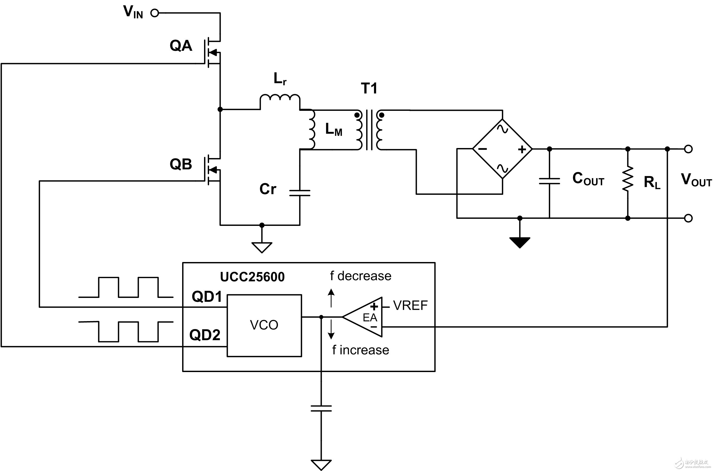
Figure 1 LLC resonant half-bridge/controller
We can normalize and simplify the use of the first harmonic approximation transfer function M(f). In Equation 4 for M(f), the normalized frequency (fn) is defined as the switching frequency divided by the resonant frequency (fO). Although only an approximation, this simplified equation is very useful in understanding how M(f) varies with input voltage, load, and switching frequency.
Adjust the DC current to adjust the LED brightness
One way to achieve LED brightness adjustment in LLC resonant LED drivers is to adjust the DC current through the LED. There is a problem with this: when the DC current changes, the output impedance of the LLC also changes. If not considered carefully, this change will cause M(f) to change, making the LED driver design more complicated.
Problems caused by load changes
Designing a half-bridge converter is not an easy task. Designers have to select the magnetizing inductance (LM) based on the ZVS requirement. They also have to adjust a1, Cr, and Lr to obtain the ideal M(f) and frequency operating range. However, M(f) changes with Q, which in turn changes with the output load (RL). See Figure 2 for details.
Variations in M(f) for a resonant LLC half-bridge LED can make voltage loop compensation and transformer selection more difficult, complex, and confusing because there are simply too many variations to consider during the design process.
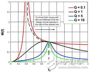
Fig. 2. Variation of M(f) with load.
The changing LLC gain curve (M(f)) causes control problems for the voltage controlled oscillator (VCO) in the feedback loop. The VCO is typically controlled by a feedback error amplifier (EA (see Figure 1)). The switching frequency decreases as the EA output increases to increase the LLC gain, and increases as the EA output decreases. Ideally, in an LLC half-bridge design, the M(f) gain should start at a minimum at its maximum switching frequency, with M(f) increasing as the frequency decreases.
The ideal M(f) range for normal operation is the portion to the right of the dashed line (see Figure 2). We call this region the inductive region, where the LLC operates under ZVS. The left side of the dashed line is the capacitive region, where there is no ZVS on the primary switch node. During large signal transients, the EA drives the VCO, requiring a lower switching frequency to increase the gain. As a result, the M(f) gain operates in the region to the left of the dashed line, which may not achieve the ideal gain and cannot meet the control loop requirements.
At this point, ZVS is lost and the feedback loop keeps the LLC controller locked in this region. Now, the feedback error amplifier tries to require a lower switching frequency to increase the gain which cannot be achieved by the power stage because the converter may operate in the region to the right of the dashed line in Figure 2. When ZVS is lost, FETs QA and QB dissipate more power and the FETs may be damaged due to overheating. To avoid this problem in the design, all M(f) curves need to be analyzed and then the minimum switching frequency (f) needs to be appropriately limited to prevent the converter (M(f)) from operating in the region to the left of the dashed line in Figure 2.
PWM brightness adjustment simplifies the design process
For LLC resonant half-bridge LED drivers that require dimming, one way to simplify the design process is to use a technique called PWM dimming. Figure 3 shows the functional schematic of an LLC converter with an LLC controller that uses this PWM dimming technique. In our example, we used the UCC25710.
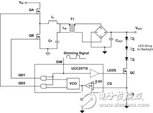
Figure 3 LLC half-bridge LED driver using PWM brightness adjustment technique.
This technique uses a fixed low frequency signal (DIM) that controls FET QC, which is logically added to the QA and QB FET drivers. When the DIM signal is high, the LED backlight string is controlled to a fixed peak current (VRS/RS). Once DIM goes low, QA, QB, and QC are turned off immediately. After QA, QB, and QC are turned off, the LED diode stops conducting, and the output capacitor (COUT) stores energy to start the next DIM cycle on time. For more details, see the waveform shown in Figure 4.
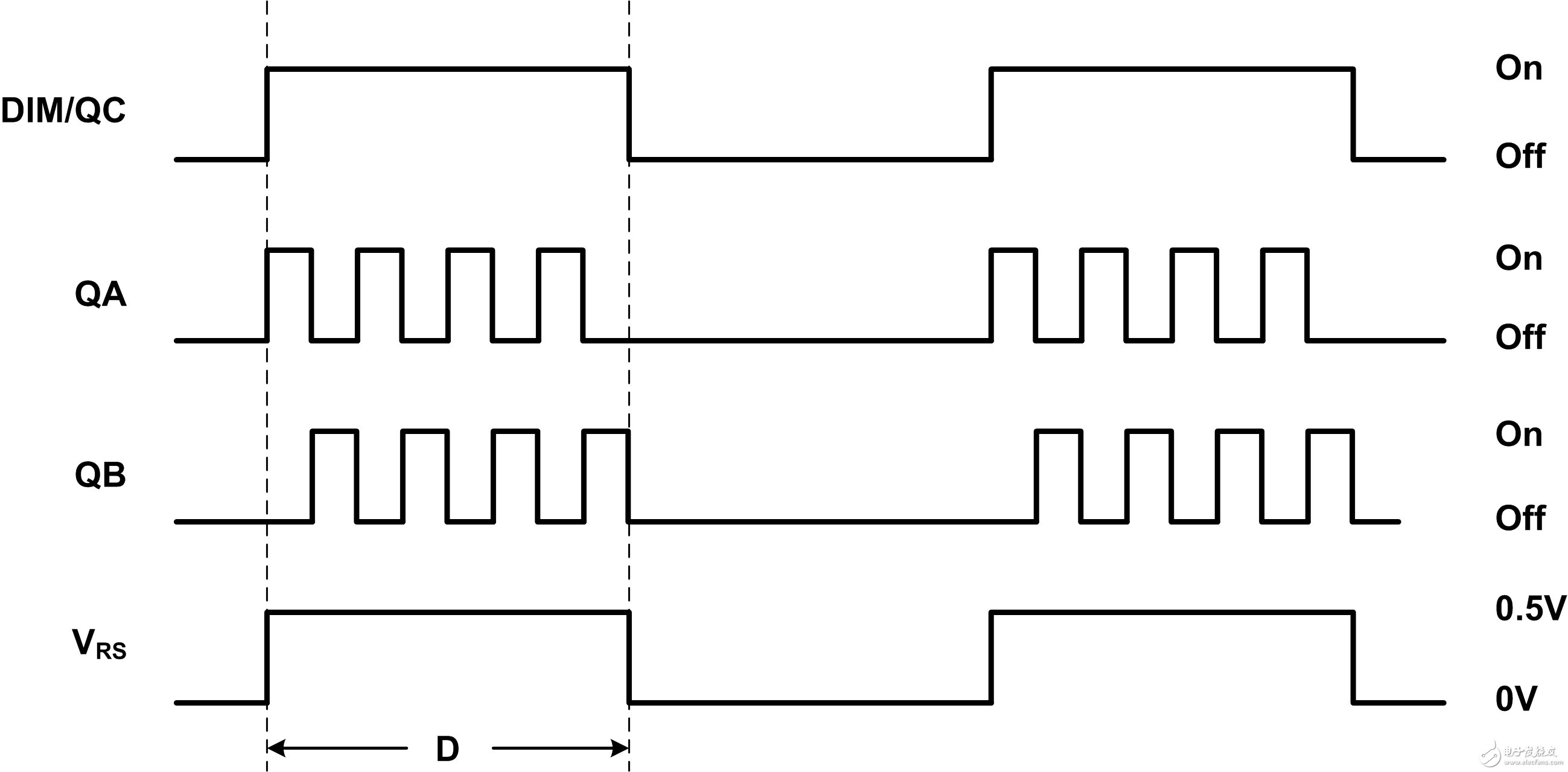
Figure 4 PWM brightness adjustment waveform
By adjusting the duty cycle (D) of the DIM signal, the average diode current (ID) can be adjusted to control the brightness of the LED.
Although the LLC resonant half-bridge powers the LED from the primary to the secondary, the load (RL) to LLC transfer function (M(f)) remains constant even though the average LED current varies with the duty cycle.
When using fixed RL and given Lr, Cr, and LM, the equivalent reflected impedance (RE) is constant and Q remains constant. This results in only one M(f) curve that varies with frequency (see Figure 5), rather than the multiple curves obtained with the traditional LED dimming method using variable RL (see Figure 2). Having only one M(f) curve to deal with in the design simplifies the design process by making loop compensation and transformer selection much simpler. In addition, another curve needs to be taken into account when setting the minimum switching frequency to ensure that ZVS is maintained. In this case, the minimum f is set to the peak of the single M(f) curve (see Figure 5).
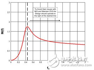
Figure 5 M(f) of driving LED using PWM brightness adjustment technology
Designing an LLC resonant half-bridge converter for LED driving is not easy. The dc/dc gain of a traditional LLC varies over a wide range with load changes. Many gain curves need to be evaluated. This makes loop compensation and transformer design/selection more complex and confusing. To simplify the design process, combining LLC with PWM brightness adjustment technology is a better choice. This is because the LLC is subject to a fixed load (RL) during power supply, but the LED current varies during brightness adjustment. As a result, the LLC gain varies less, making loop compensation and transformer selection/design simpler.
Previous article:Jinko Electronics releases two LM-80 standard LED products
Next article:A Brief Discussion on High-Power LED and Its Application
- Popular Resources
- Popular amplifiers
- ROHM develops the second generation of MUS-IC™ series audio DAC chips suitable for high-resolution audio playback
- ADALM2000 Experiment: Transformer-Coupled Amplifier
- High signal-to-noise ratio MEMS microphone drives artificial intelligence interaction
- Advantages of using a differential-to-single-ended RF amplifier in a transmit signal chain design
- ON Semiconductor CEO Appears at Munich Electronica Show and Launches Treo Platform
- ON Semiconductor Launches Industry-Leading Analog and Mixed-Signal Platform
- Analog Devices ADAQ7767-1 μModule DAQ Solution for Rapid Development of Precision Data Acquisition Systems Now Available at Mouser
- Domestic high-precision, high-speed ADC chips are on the rise
- Microcontrollers that combine Hi-Fi, intelligence and USB multi-channel features – ushering in a new era of digital audio
- Intel promotes AI with multi-dimensional efforts in technology, application, and ecology
- ChinaJoy Qualcomm Snapdragon Theme Pavilion takes you to experience the new changes in digital entertainment in the 5G era
- Infineon's latest generation IGBT technology platform enables precise control of speed and position
- Two test methods for LED lighting life
- Don't Let Lightning Induced Surges Scare You
- Application of brushless motor controller ML4425/4426
- Easy identification of LED power supply quality
- World's first integrated photovoltaic solar system completed in Israel
- Sliding window mean filter for avr microcontroller AD conversion
- What does call mean in the detailed explanation of ABB robot programming instructions?
- Ultrasound patch can continuously and noninvasively monitor blood pressure
- Ultrasound patch can continuously and noninvasively monitor blood pressure
- Europe's three largest chip giants re-examine their supply chains
- Europe's three largest chip giants re-examine their supply chains
- Breaking through the intelligent competition, Changan Automobile opens the "God's perspective"
- The world's first fully digital chassis, looking forward to the debut of the U7 PHEV and EV versions
- Design of automotive LIN communication simulator based on Renesas MCU
- When will solid-state batteries become popular?
- Adding solid-state batteries, CATL wants to continue to be the "King of Ning"
- The agency predicts that my country's public electric vehicle charging piles will reach 3.6 million this year, accounting for nearly 70% of the world
- Integrated circuit detection method
- When using an oscilloscope probe to measure the AC waveform between the two ends of a component, how should the probe ground wire be connected?
- 【ST NUCLEO-H743ZI Review】(2)Ethernet Test
- TI.com Online Purchasing Special (Smart Building) has a limited time offer, with discounts as low as 30%!
- Play with pyboardCN V2 - Comparison with Nano board
- [Teardown] Apple Watch Series 6, with a bigger battery, thinner ceramic and sapphire casings, stronger and more wear-resistant!
- Development board auction, one new one per day! Today's auction development board: NXP LPC800
- DLP Lightcrafter 4500 EVM FAQ Summary
- NRF24L01 module usage
- AD 20.2.4 x64

 EL5724IRE-T13


 京公网安备 11010802033920号