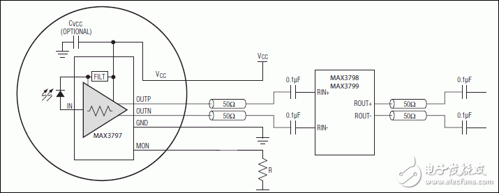
The MAX3797 is a low-power transimpedance amplifier designed for optical transmission systems with data rates up to 10.3125Gbps and using PIN diodes.
The MAX3797 integrates an automatic gain control (AGC) architecture that provides a nominal small-signal transimpedance of 5.5kΩ. Input-referred noise is typically 1.25μARMS, which reflects a theoretical sensitivity of -14.8dBm OMA at a pin code (z = 0.55, re = 3) photodetector with a bit error rate (BER) of 10-12.
Make optical components using TO-46 or TO-56 packages with small chip size of 1mm x 0.76mm.
Key Features
Supply and temperature stable sensitivity
Up to 10.3125Gbps (NRZ) operation
Support capacitor-free ROSA
AGC gain is 5.5kΩ
3.3V single power supply
105mW power consumption
Wide-Bandwidth Current Monitor Enables RSSI-Based LOS Implementation
Die size 1mm x 0.76mm
chart

Typical Application Circuit
Previous article:MAX14954 Quad-Channel Equalizer/Redriver
Next article:MAX9240 25-bit GMSL deserializer
Recommended ReadingLatest update time:2024-11-17 02:34


- Popular Resources
- Popular amplifiers
-
 Operational Amplifier Practical Reference Handbook (Edited by Liu Changsheng, Zhao Mingying, Liu Xu, etc.)
 -
 A Complete Illustrated Guide to Operational Amplifier Applications (Written by Wang Zhenhong)
 -
 Design of isolated error amplifier chip for switching power supply_Zhang Rui
 -
 DAM medium wave transmitter high frequency power amplifier module test platform_Tian Tian
- High signal-to-noise ratio MEMS microphone drives artificial intelligence interaction
- Advantages of using a differential-to-single-ended RF amplifier in a transmit signal chain design
- ON Semiconductor CEO Appears at Munich Electronica Show and Launches Treo Platform
- ON Semiconductor Launches Industry-Leading Analog and Mixed-Signal Platform
- Analog Devices ADAQ7767-1 μModule DAQ Solution for Rapid Development of Precision Data Acquisition Systems Now Available at Mouser
- Domestic high-precision, high-speed ADC chips are on the rise
- Microcontrollers that combine Hi-Fi, intelligence and USB multi-channel features – ushering in a new era of digital audio
- Using capacitive PGA, Naxin Micro launches high-precision multi-channel 24/16-bit Δ-Σ ADC
- Fully Differential Amplifier Provides High Voltage, Low Noise Signals for Precision Data Acquisition Signal Chain
- Innolux's intelligent steer-by-wire solution makes cars smarter and safer
- 8051 MCU - Parity Check
- How to efficiently balance the sensitivity of tactile sensing interfaces
- What should I do if the servo motor shakes? What causes the servo motor to shake quickly?
- 【Brushless Motor】Analysis of three-phase BLDC motor and sharing of two popular development boards
- Midea Industrial Technology's subsidiaries Clou Electronics and Hekang New Energy jointly appeared at the Munich Battery Energy Storage Exhibition and Solar Energy Exhibition
- Guoxin Sichen | Application of ferroelectric memory PB85RS2MC in power battery management, with a capacity of 2M
- Analysis of common faults of frequency converter
- In a head-on competition with Qualcomm, what kind of cockpit products has Intel come up with?
- Dalian Rongke's all-vanadium liquid flow battery energy storage equipment industrialization project has entered the sprint stage before production
- Allegro MicroSystems Introduces Advanced Magnetic and Inductive Position Sensing Solutions at Electronica 2024
- Car key in the left hand, liveness detection radar in the right hand, UWB is imperative for cars!
- After a decade of rapid development, domestic CIS has entered the market
- Aegis Dagger Battery + Thor EM-i Super Hybrid, Geely New Energy has thrown out two "king bombs"
- A brief discussion on functional safety - fault, error, and failure
- In the smart car 2.0 cycle, these core industry chains are facing major opportunities!
- Rambus Launches Industry's First HBM 4 Controller IP: What Are the Technical Details Behind It?
- The United States and Japan are developing new batteries. CATL faces challenges? How should China's new energy battery industry respond?
- Murata launches high-precision 6-axis inertial sensor for automobiles
- Ford patents pre-charge alarm to help save costs and respond to emergencies
- The storage and downloading of time values sent by customers require sum verification or CRC verification
- EPWM CMPA register configuration problem
- Allegro's latest solution for 48v system
- EEWORLD University Hall----Live Replay: Microchip Security Series 12 - PolarFire? SoC FPGA Secure Boot
- "Praise my country": Let's gather together and talk about the useful domestic microcontrollers
- Ling Embedded Talent Recruitment is in full swing! Don’t run~ It’s you~
- A correct schematic does not necessarily produce a correct PCB design
- I hit a wall when I used EasyEDA for the first time
- [Repost] Understand the control principle and classification of switching power supplies in one article
- Kalman filter and UKF

 Operational Amplifier Practical Reference Handbook (Edited by Liu Changsheng, Zhao Mingying, Liu Xu, etc.)


 京公网安备 11010802033920号