1. Design of smart home security system based on single chip microcomputer
Abstract: This paper introduces a design of a multi-node home security system with AT89S52 single-chip microcomputer as the control core, which transmits information through DTMF public telephone network and CAN bus. This intelligent home security system integrates fire prevention, anti-theft and anti-gas, and can realize automatic detection and automatic voice dialing alarm. The DTMF transceiver circuit, call circuit and CAN bus transmission circuit are introduced in detail. The experimental results show that this system is practical, the information transmission is real-time and reliable, and it is suitable for home security or other security systems.
1 Introduction
The current security system can be realized with the help of computer technology, IC card technology, communication technology, etc. The application of CAN bus in security system has played a good role in promoting the development of home intelligence. The application of DTMF technology in security system does not require special wiring, does not occupy radio frequency resources, and has no electromagnetic pollution. This paper designs a new intelligent home security system based on CAN bus and DTMF technology with AT89S52 microcontroller as the core, which improves the real-time and reliability of the original community security system to a new level. This system can monitor the security environment of the entire home in real time, and the monitoring scope includes a series of unsafe factors such as indoor anti-theft, fire alarm, gas leakage, etc. Once the above accidents occur, the alarm system will issue corresponding alarm information, broadcast the alarm category with voice, and provide alarm voice to remote users and relevant departments.
2 Overall system composition
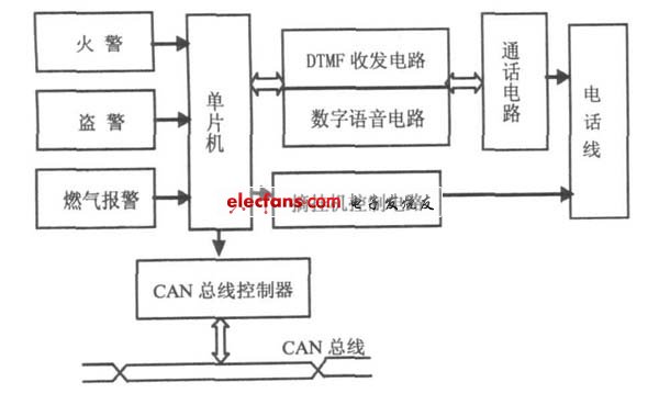
The system block diagram is shown in Figure 1. The single-chip microcomputer controls the DTMF transceiver circuit, digital voice circuit, and on-hook and off-hook control circuit. The detector can quickly and accurately detect abnormal conditions in the residence, and notify the controller in time after confirmation. The single-chip microcomputer then controls the telephone interface circuit to simulate off-hook, automatically dial the pre-set telephone number for voice alarm and notify the management center. When the other party responds, the alarm state is automatically restored.

Figure 1 Block diagram of home security system
3 Hardware Design
The main control part of the system uses AT89S52 single-chip microcomputer, and there is no need to expand external memory. The watchdog circuit uses a programmable serial EEPROM - X25045. X25045 stores data information such as flag field, phone number, alarm code, system settings, etc. The digital voice circuit uses the digital voice chip ISD1420. In the system, ISD1420 is only used as a basic recording and playback circuit, so all address lines are set to 0, so the starting address of playback is 0. The voice signal is picked up by the electret microphone and input from the MIC and MIC REF ends to the amplifier inside the chip for amplification. The audio signal after the power amplifier is used from SP+ to connect to the call circuit to send out the voice signal.
3.1 Ring detection and analog off-hook and off-hook unit
The system is always in monitoring state at both ends of the telephone line, which will not affect the normal operation of the telephone. When the system receives a ringing signal, it will perform a ringing detection. The ringing signal is connected to the P3.4 port of AT89S52 after passing through three inverters. If no one answers after 5 rings, the system enters the automatic off-hook state. The P1.2 pin of the microcontroller outputs a high level, the transistor V501 is turned on, and the relay K1 is activated, and the load resistor is connected to the circuit to simulate off-hook. After that, a current greater than 10mA will appear on the telephone line. After the exchange center detects this current, it will no longer output a ringing signal but turn to connect the phone. If the ringing signal disappears before reaching the preset value, the count value of the microcontroller is reset to zero and the controller does not act.
3.2 DTMF transceiver unit
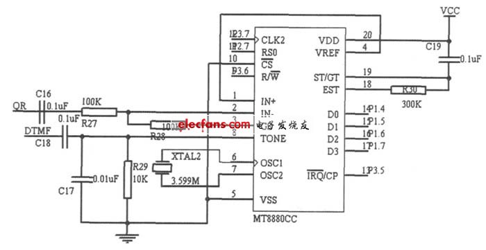
The DTMF transceiver circuit uses the DTMF signal encoding/decoding chip MT8880[5]. The microcontroller dials the phone number through the DTMF transceiver circuit to make a telephone alarm. The DTMF transceiver circuit is shown in Figure 2.

Figure 2 DTMF transceiver circuit
MT8880 provides an interface connected to a microprocessor to control its transmission, reception and working mode. Its receiving part uses a single-ended input, which is composed of R27, R28 and C16. Its input voltage gain is 1. The gain of the input signal can be adjusted by changing R28. Its transmitting part is composed of R29, C17, C18 and XTAL2. Its control part is composed of R30 and C19. IRQ/CP is connected to the P3.5 pin of the microcontroller. When MT8880 receives a valid dual-tone multi-frequency signal, the microcontroller performs interrupt processing. The IN- terminal of MT8880 is connected to the QR terminal of the call circuit TEA1062, and the TONE terminal of MT8880 is connected to the DTMF terminal of TEA1062.
3.3 Call Unit
The call circuit uses the dedicated call integrated circuit TEA1062 for telephones. When sending a call, the voice signal (from ISD1420) is input through the M IC + pin, and the DTMF signal (from MT8880) is input through the DTMF pin. After being amplified by TEA1062, they are sent to the telephone line from the LN pin. When receiving a call, the signal is input from the IR pin through the sidetone cancellation network, and is output from the QR pin after amplification. It is divided into two paths: one is sent to the ANA IN terminal of ISD1420 for voice recording, and the other is sent to the IN - terminal of MT8880 to extract the DTMF signal.
3.4 CAN bus data transmission unit
The CAN bus data transmission unit consists of two parts, one is the CAN controller, which realizes the interaction and control of the bus data, and the other is the CAN data transceiver, which realizes the network transmission of data.
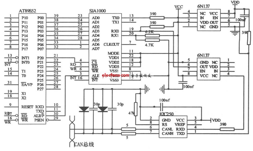
The single-chip microcomputer AT89S52 accesses the bus by controlling the CAN controller, and is also responsible for the measurement and control of the functional units. The CAN bus interface circuit is shown in Figure 3.

Figure 3 CAN bus interface circuit
AT89S52 accesses CAN controller SJA1000 through interrupt mode. In order to enhance the anti-interference ability of CAN bus nodes, SJA1000 is connected to CAN bus driver PCA82C50 through high-speed optocoupler 6N137. CANH and CANL pins of PCA82C50 are connected to CAN bus through a 5Ω resistor respectively, which can limit the current and prevent PCA82C50 from being impacted by overcurrent.
4 Software Design
The system software adopts a modular design, mainly including the main program module, CAN communication module, ringing detection module, voice alarm module, DTMF transceiver module, etc. Here we mainly introduce the main program and CAN communication module design.
4.1 Main program design
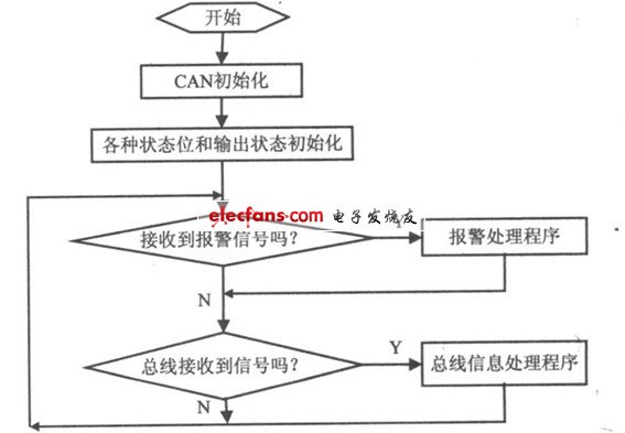
The main program mainly completes the call of each functional module, detects the system input, and then makes judgments and processes according to the system status. Before the program enters the main loop, it is necessary to perform necessary initialization, such as MT8880, ISD1420, SJA1000, related flags, etc. The main program flow is shown in Figure 4.

Figure 4 Main program flow chart
Previous article:Object positioning detection circuit schematic
Next article:Smart Home Design Solution Reference Collection (Part 3)
- Popular Resources
- Popular amplifiers
- High signal-to-noise ratio MEMS microphone drives artificial intelligence interaction
- Advantages of using a differential-to-single-ended RF amplifier in a transmit signal chain design
- ON Semiconductor CEO Appears at Munich Electronica Show and Launches Treo Platform
- ON Semiconductor Launches Industry-Leading Analog and Mixed-Signal Platform
- Analog Devices ADAQ7767-1 μModule DAQ Solution for Rapid Development of Precision Data Acquisition Systems Now Available at Mouser
- Domestic high-precision, high-speed ADC chips are on the rise
- Microcontrollers that combine Hi-Fi, intelligence and USB multi-channel features – ushering in a new era of digital audio
- Using capacitive PGA, Naxin Micro launches high-precision multi-channel 24/16-bit Δ-Σ ADC
- Fully Differential Amplifier Provides High Voltage, Low Noise Signals for Precision Data Acquisition Signal Chain
- Innolux's intelligent steer-by-wire solution makes cars smarter and safer
- 8051 MCU - Parity Check
- How to efficiently balance the sensitivity of tactile sensing interfaces
- What should I do if the servo motor shakes? What causes the servo motor to shake quickly?
- 【Brushless Motor】Analysis of three-phase BLDC motor and sharing of two popular development boards
- Midea Industrial Technology's subsidiaries Clou Electronics and Hekang New Energy jointly appeared at the Munich Battery Energy Storage Exhibition and Solar Energy Exhibition
- Guoxin Sichen | Application of ferroelectric memory PB85RS2MC in power battery management, with a capacity of 2M
- Analysis of common faults of frequency converter
- In a head-on competition with Qualcomm, what kind of cockpit products has Intel come up with?
- Dalian Rongke's all-vanadium liquid flow battery energy storage equipment industrialization project has entered the sprint stage before production
- Allegro MicroSystems Introduces Advanced Magnetic and Inductive Position Sensing Solutions at Electronica 2024
- Car key in the left hand, liveness detection radar in the right hand, UWB is imperative for cars!
- After a decade of rapid development, domestic CIS has entered the market
- Aegis Dagger Battery + Thor EM-i Super Hybrid, Geely New Energy has thrown out two "king bombs"
- A brief discussion on functional safety - fault, error, and failure
- In the smart car 2.0 cycle, these core industry chains are facing major opportunities!
- The United States and Japan are developing new batteries. CATL faces challenges? How should China's new energy battery industry respond?
- Murata launches high-precision 6-axis inertial sensor for automobiles
- Ford patents pre-charge alarm to help save costs and respond to emergencies
- New real-time microcontroller system from Texas Instruments enables smarter processing in automotive and industrial applications
- Use T0 timer to write back and forth water lamp, but why only one lamp continues to light up?
- Generate DSP code using MATLAB
- Digital Communication FPGA Development and Design Platform.pdf
- Timing diagram
- Can passive crystal oscillators of the same frequency be directly replaced? Is there anything I should pay attention to?
- LTC3108 Circuit Design
- EEWORLD University----STM32F7 online training (OLT)
- Share the issues that young electronic engineers are most concerned about. What are you concerned about?
- BK9521 wireless chip transmitter circuit
- EEWORLD University Hall----TI motor driver chip latest technical advantages and applications

 ARM Cortex-M4+Wi-Fi MCU Application Guide (Embedded Technology and Application Series) (Guo Shujun)


 京公网安备 11010802033920号