Modern integrated operational amplifiers (op amps) and instrumentation amplifiers (in-amps) offer many benefits to design engineers compared to discrete devices. While providing many clever, useful, and attractive circuits, it is often the case that in the haste to assemble a circuit, some very basic issues are overlooked, resulting in a circuit that does not perform the intended function - or may not work at all.
This article discusses some of the most common application problems and provides practical solutions.
Lack of DC bias current return path when AC coupling
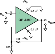
One of the most commonly encountered application problems is the lack of a DC return path to provide bias current in an AC-coupled op amp or instrumentation amplifier circuit. In Figure 1, a capacitor is connected in series with the op amp's non-inverting input to achieve AC coupling, which is a simple way to isolate the DC component of the input voltage (VIN). This is especially useful in high-gain applications where even a small DC voltage at the op amp input can limit the dynamic range or even cause output saturation. However, adding capacitive coupling to a high-impedance input without providing a DC path for the current at the non-inverting input can cause problems.

Figure 1. Incorrect AC-coupled op amp input.
In effect, the input bias current flows into the coupled capacitor and charges it until it exceeds the common-mode voltage rating of the amplifier input circuit or limits the output. Depending on the polarity of the input bias current, the capacitor charges to either the positive or negative supply voltage. The closed-loop DC gain of the amplifier amplifies the bias voltage.
This process can take a very long time. For example, a field effect transistor (FET) input amplifier with a 1 pA bias current coupled to a 0.1 µF capacitor will charge at a rate I/C of 10-12/10-7 = 10 µV/s, or 600 µV per minute. With a gain of 100, the output will drift 0.06 V per minute. Thus, normal lab testing (using an AC-coupled oscilloscope) will not detect this problem until the circuit has failed hours later. Clearly, it is important to avoid this problem altogether.

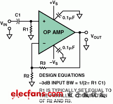
Figure 2. Proper AC-coupling of dual-supply op amp inputs.
Figure 2 shows a simple solution to this common problem. Here, a resistor is connected between the op amp input and ground to provide a return path to ground for the input bias current. To minimize the offset voltage caused by the input bias current, when using a bipolar op amp, the bias currents at its two inputs should be equal, so the resistance value of R1 should usually be set to equal the parallel resistance of R2 and R3.
However, it should be noted that resistor R1 will always introduce some noise into the circuit, so a trade-off must be made between the circuit input impedance, the size of the input coupling capacitor, and the Johnson noise caused by the resistor. Typical resistor values are generally between 100,000Ω and 1 MΩ.
Similar problems can also occur in instrumentation amplifier circuits. Figure 3 shows an instrumentation amplifier circuit that uses two capacitors for AC coupling, without providing a return path for the input bias current. This problem is common in instrumentation amplifier circuits powered by dual power supplies (Figure 3a) and single power supplies (Figure 3b).

Figure 3. Example of an AC-coupled instrumentation amplifier that does not function.
This type of problem can also occur in transformer coupled amplifier circuits, as shown in Figure 4, if a DC return path to ground is not provided in the transformer secondary circuit.

Figure 4. Inoperative transformer-coupled instrumentation amplifier circuit.
Figures 5 and 6 show simple solutions for these circuits. Here, a high-value resistor (RA, RB) is connected between each input and ground. This is a simple and practical solution for dual-supply instrumentation amplifier circuits.

Figure 5. A high-value resistor is connected from each input to ground to provide the necessary bias current return path.
a. Dual power supply, b. Single power supply
These two resistors provide a discharge path for the input bias current. In the dual-supply example shown in Figure 5, both inputs are referenced to ground. In the single-supply example shown in Figure 5b, both inputs are referenced to either ground (VCM is grounded) or to a bias voltage, usually half the maximum input voltage. The
same principle can be applied to transformer-coupled input circuits (see Figure 6), except that the transformer secondary has a center tap, which can be grounded or connected to VCM.
In this circuit, a small offset voltage error will be generated due to the mismatch between the two input resistors and/or the mismatch of the input bias current at both ends. In order to minimize the offset error, another resistor can be connected between the two inputs of the instrumentation amplifier (i.e., bridged between the two resistors), with a resistance value of about 1/10th of the first two resistors (but still large compared to the differential source impedance).

Figure 6. Proper transformer input coupling for an instrumentation amplifier.
Provides reference voltage for instrumentation amplifiers, operational amplifiers, and ADCs
Figure 7 shows a single-supply circuit for an instrumentation amplifier driving a single-ended input analog-to-digital converter (ADC). The amplifier's reference voltage provides a bias voltage for zero differential input, while the ADC's reference voltage provides a scale factor. A simple RC low-pass antialiasing filter is often connected between the instrumentation amplifier's output and the ADC's input to reduce out-of-band noise. Designers often want to use simple methods, such as resistor dividers, to provide reference voltages for the instrumentation amplifier and ADC. As a result, errors can occur when using some instrumentation amplifiers.

Figure 7. Typical single-supply circuit for an instrumentation amplifier driving an ADC.
Previous article:Microcontroller entry design: a simple and fun heart rate meter
Next article:Summary of key issues in amplifier circuit design (Part 2)
Recommended ReadingLatest update time:2024-11-16 17:55


- Popular Resources
- Popular amplifiers
-
 Operational Amplifier Practical Reference Handbook (Edited by Liu Changsheng, Zhao Mingying, Liu Xu, etc.)
 -
 A Complete Illustrated Guide to Operational Amplifier Applications (Written by Wang Zhenhong)
 -
 Design of isolated error amplifier chip for switching power supply_Zhang Rui
 -
 DAM medium wave transmitter high frequency power amplifier module test platform_Tian Tian
- High signal-to-noise ratio MEMS microphone drives artificial intelligence interaction
- Advantages of using a differential-to-single-ended RF amplifier in a transmit signal chain design
- ON Semiconductor CEO Appears at Munich Electronica Show and Launches Treo Platform
- ON Semiconductor Launches Industry-Leading Analog and Mixed-Signal Platform
- Analog Devices ADAQ7767-1 μModule DAQ Solution for Rapid Development of Precision Data Acquisition Systems Now Available at Mouser
- Domestic high-precision, high-speed ADC chips are on the rise
- Microcontrollers that combine Hi-Fi, intelligence and USB multi-channel features – ushering in a new era of digital audio
- Using capacitive PGA, Naxin Micro launches high-precision multi-channel 24/16-bit Δ-Σ ADC
- Fully Differential Amplifier Provides High Voltage, Low Noise Signals for Precision Data Acquisition Signal Chain
- Innolux's intelligent steer-by-wire solution makes cars smarter and safer
- 8051 MCU - Parity Check
- How to efficiently balance the sensitivity of tactile sensing interfaces
- What should I do if the servo motor shakes? What causes the servo motor to shake quickly?
- 【Brushless Motor】Analysis of three-phase BLDC motor and sharing of two popular development boards
- Midea Industrial Technology's subsidiaries Clou Electronics and Hekang New Energy jointly appeared at the Munich Battery Energy Storage Exhibition and Solar Energy Exhibition
- Guoxin Sichen | Application of ferroelectric memory PB85RS2MC in power battery management, with a capacity of 2M
- Analysis of common faults of frequency converter
- In a head-on competition with Qualcomm, what kind of cockpit products has Intel come up with?
- Dalian Rongke's all-vanadium liquid flow battery energy storage equipment industrialization project has entered the sprint stage before production
- Allegro MicroSystems Introduces Advanced Magnetic and Inductive Position Sensing Solutions at Electronica 2024
- Car key in the left hand, liveness detection radar in the right hand, UWB is imperative for cars!
- After a decade of rapid development, domestic CIS has entered the market
- Aegis Dagger Battery + Thor EM-i Super Hybrid, Geely New Energy has thrown out two "king bombs"
- A brief discussion on functional safety - fault, error, and failure
- In the smart car 2.0 cycle, these core industry chains are facing major opportunities!
- The United States and Japan are developing new batteries. CATL faces challenges? How should China's new energy battery industry respond?
- Murata launches high-precision 6-axis inertial sensor for automobiles
- Ford patents pre-charge alarm to help save costs and respond to emergencies
- New real-time microcontroller system from Texas Instruments enables smarter processing in automotive and industrial applications
- FPGA Entry Series Digital Tube
- Analog Dialogue Volume 55 Issue 3 is now online! Come and get your source of inspiration~
- 51 delay problem
- Get a gift for your evaluation! Hands-on experience: Recruiting TI millimeter-wave radar testers from all over the Internet
- How does Allegro's built-in package library identify which type of device it belongs to?
- STM8 Little Frog: Return to the Arena
- What are some good ways to transform various periodic waveforms into square waves that can be recognized by microcontrollers?
- General Design Considerations for Embedded Systems
- CH340 circuit improves working stability and anti-interference
- Schematic diagram of numworks

 Operational Amplifier Practical Reference Handbook (Edited by Liu Changsheng, Zhao Mingying, Liu Xu, etc.)


 京公网安备 11010802033920号