随着对大功率低电压本安电源的需求增大,基本本安Buck变换器就需要进一步提高输出功率。但是要想提高输出功率,增大输出电流,可以使变换器输出端电感电容的容量增加,但是这样很容易引燃爆炸性气体,降低本质安全性能;再者可以通过提高开关频率来实现,一方面能够减小为满足输出纹波电压要求所需的电感和电容取值,因此也有利于本质安全,但另一方面提高开关频率却降低了变换器的效率,导致最大电感电流增大而不利于本质安全。此外提高开关频率还可能导致电容器的实际有效容量显著下降而影响滤波效果,并且过高的开关频率不仅不易实现,而且电路稳定性也会受影响。为此,本文提出在基本本安Buck变换器输出端采用LC滤波电路的思想,使得本安Buck变换器在小电感、小电容的情况下,就能既满足电气性能指标,又能满足本质安全性能指标,且能有效提高输出功率。
1 Composition and working principle of basic Buck converter
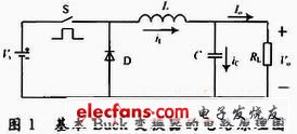
The circuit diagram of the basic Buck converter is shown in Figure 1. It is mainly composed of a switch tube S, a freewheeling diode D, an energy storage inductor L and a filter capacitor C.

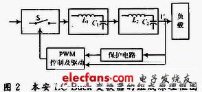
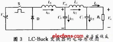
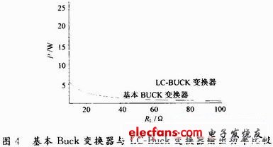
When the switch tube S is turned on, the freewheeling diode D is cut off due to the reverse voltage, and the current iL flowing through the inductor L increases linearly. The current flowing through the load resistor RL is Io, and the output voltage across RL is Vo, with a positive polarity at the top and a negative polarity at the bottom, as shown in Figure 1. When iL>Io, the capacitor C is in a charging state. When the switch tube S is turned off, the freewheeling diode D is turned on due to the forward voltage, and iL decreases linearly. When iL 2 High-power intrinsically safe LC-Buck converter 2.1 Composition of high-power intrinsically safe LC-Buck converter From the above content, it can be seen that the main factors that affect both electrical indicators and intrinsic safety performance indicators are the inductance and capacitance values and the selection of switching frequency. Therefore, the design of intrinsically safe switching converters is actually to ensure that the circuit parameters meet the requirements of electrical indicators, and to select appropriate switching frequency, inductance and output filter capacitors so that when disconnection and short circuit occur due to faults, the discharge energy generated is small enough not to ignite explosive gases. Due to the existence of the above contradictions, this paper adds an LC filtering circuit to the output end of the basic Buck converter, so that the Buck converter can meet the electrical performance indicators and intrinsic safety performance indicators at the same time when the inductance and capacitance values are not large, and the output power can be improved. The block diagram of the composition principle of the intrinsically safe LC-Buck converter is shown in Figure 2. 2.2 Basic working principle of intrinsically safe LC-Buck converter The intrinsically safe LC-Buck converter is composed of a basic Buck converter and a second-order L, C low-pass filter. Its main circuit structure is shown in Figure 3. As can be seen from Figure 3, the LC-Buck converter is composed of an additional L, C filter circuit at the output end of the basic Buck converter, and is mainly composed of the following parts: a switch tube S controlled by PWM; a freewheeling diode D; an energy storage inductor L1; an output filter inductor L2; output filter capacitors C1, C2 and a load resistor RL. Among them, Vi is the input DC voltage; Vo1 is the first-stage output voltage, and Vo is the second-stage output voltage. The working principle of the LC-Buck converter is analyzed in a switching cycle. When the switch tube S is turned on, the freewheeling diode D is cut off due to the reverse voltage, and the current iL1 flowing through the inductor L1 increases linearly. The energy storage inductor L1 converts electrical energy into magnetic energy and stores it in the inductor L1. When iL1>Io, the capacitor C1 enters the charging state. When the switch tube S is turned off, since the current flowing through the energy storage inductor L1 cannot change suddenly, a self-inductance potential with a negative left and a positive right is induced at both ends of L1, causing the freewheeling diode D to turn on, and L1 converts the originally stored magnetic energy into electrical energy to supply the load. At this time, the inductor current iL1 decreases linearly, and when iL1 3 Experimental verification When the input voltage, switching frequency, equivalent capacitance and equivalent inductance are the same, calculate the maximum output power of the two converters. The specific indicators are as follows: The input voltage is yi = 21 ~ 27 V, the operating frequency is f = 300 kHz, and the load resistance RL ranges from 10 to 100 Ω. The maximum equivalent capacitance is Ce, max = 5 μF, the maximum equivalent inductance is Le, max = 20 μF, and the maximum ripple voltage is Vpp, max = 1% Vo. L1 = 18 μH, C1 = 1 μF, L2 = 15 μH, C2 = 0.6 μF. In a certain load variation range, the relationship curve between the output power and load resistance of the basic intrinsically safe Buck converter and the intrinsically safe LC-Buck converter is shown in Figure 4. As can be seen from Figure 4, under the same input conditions and the same equivalent inductance and equivalent capacitance conditions, the maximum output power of the intrinsically safe LC-Buck converter is much greater than the maximum output power of the basic intrinsically safe Buck converter. This shows that using LC filtering at the output end of the basic intrinsically safe Buck converter can greatly improve the output power of the intrinsically safe Buck converter and effectively reduce the capacity of the inductance and capacitance of the energy storage components. This reflects the superiority of the LC-Buck converter. 4 Conclusion This paper first analyzes the composition and working principle of the basic Buck converter; secondly, it proposes a solution to increase the output power of the converter by using an intrinsically safe Buck converter with LC filtering, and analyzes the composition and principle of the LC-Buck converter. Finally, the conclusion that the LC-Buck converter can greatly increase the output power of the intrinsically safe circuit is verified through experiments.


Previous article:Low-cost LED driver with 92% efficiency is now possible
Next article:Design and implementation of vending machine based on embedded system
- Popular Resources
- Popular amplifiers
- USB Type-C® and USB Power Delivery: Designed for extended power range and battery-powered systems
- ROHM develops the second generation of MUS-IC™ series audio DAC chips suitable for high-resolution audio playback
- ADALM2000 Experiment: Transformer-Coupled Amplifier
- High signal-to-noise ratio MEMS microphone drives artificial intelligence interaction
- Advantages of using a differential-to-single-ended RF amplifier in a transmit signal chain design
- ON Semiconductor CEO Appears at Munich Electronica Show and Launches Treo Platform
- ON Semiconductor Launches Industry-Leading Analog and Mixed-Signal Platform
- Analog Devices ADAQ7767-1 μModule DAQ Solution for Rapid Development of Precision Data Acquisition Systems Now Available at Mouser
- Domestic high-precision, high-speed ADC chips are on the rise
- Intel promotes AI with multi-dimensional efforts in technology, application, and ecology
- ChinaJoy Qualcomm Snapdragon Theme Pavilion takes you to experience the new changes in digital entertainment in the 5G era
- Infineon's latest generation IGBT technology platform enables precise control of speed and position
- Two test methods for LED lighting life
- Don't Let Lightning Induced Surges Scare You
- Application of brushless motor controller ML4425/4426
- Easy identification of LED power supply quality
- World's first integrated photovoltaic solar system completed in Israel
- Sliding window mean filter for avr microcontroller AD conversion
- What does call mean in the detailed explanation of ABB robot programming instructions?
- 2024 China Automotive Charging and Battery Swapping Ecosystem Conference held in Taiyuan
- State-owned enterprises team up to invest in solid-state battery giant
- The evolution of electronic and electrical architecture is accelerating
- The first! National Automotive Chip Quality Inspection Center established
- BYD releases self-developed automotive chip using 4nm process, with a running score of up to 1.15 million
- GEODNET launches GEO-PULSE, a car GPS navigation device
- Should Chinese car companies develop their own high-computing chips?
- Infineon and Siemens combine embedded automotive software platform with microcontrollers to provide the necessary functions for next-generation SDVs
- Continental launches invisible biometric sensor display to monitor passengers' vital signs
- Another technical solution for power-type plug-in hybrid: A brief discussion on Volvo T8 plug-in hybrid technology
- [Nucleo G071 Review] I2C OLED&AD Collection
- The Three Realms of Oscilloscopes.pdf
- Summary of DSP 28377 online upgrade examples
- About MSP430F5438A upgrade failure
- Yesterday there was a strong wind and heavy rain, but today there is no wind or rain and no clear sky
- DJI, Huawei and other FPGA written test interview video answers
- FPGA Implementation of ECT Image Reconstruction Algorithm
- Designing Current Loops Using the MSP430 MCU Smart Analog Combo
- The difference between HISPI and MIPI protocols.
- Can the analog watchdog of stm32f103ve be used for power-off detection?

 LM316H


 京公网安备 11010802033920号