Mechanical and digital potentiometers have uncertain end-to-end tolerances, with Maxim's digital potentiometers typically having an end-to-end resistance tolerance of 20% to 30%. This resistance variation can cause problems when the digital potentiometer is connected in series with other resistors to form a voltage divider network, causing voltage changes that exceed the allowable error range.
This application note discusses a ratiometric circuit design method that converts the resistance variation into an acceptable current change, which effectively cancels the voltage change. In the circuit shown here, the voltage output is determined by the ratio of the potentiometer, and the temperature coefficient can also be well controlled in the design.

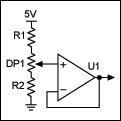
Figure 1. Basic Block Diagram
Now consider the same calculation with different wiper resistances. If the potentiometer is 37.5kΩ, the top voltage is 4.46V and the low end is 3.25V; if the potentiometer is 62.5kΩ, the top voltage is 4.54V and the low end voltage is 2.79V. In this circuit, due to the large end-to-end resistance variation of the potentiometer, this basic architecture cannot be used to solve the voltage variation problem.
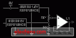
The circuit in Figure 2 simply uses the resistance ratio of the potentiometer to divide the voltage.

Figure 2. Alternative design with two voltage references
The introduction of two voltage references in the circuit allows the error and temperature coefficient to be controlled. The absolute end-to-end deviation of the digital potentiometer will change the loop current but not the voltage. The output voltage changes proportionally, depending only on the resistor ratio of the potentiometer wiper position.
Both references control the output voltage through feedback, and R2 (25K to 50K) determines the source current of the two references. The bypass capacitor is discussed in the data sheet of Maxim digital potentiometers, and the capacitor can be added according to the layout.
Reference address:How to Eliminate Voltage Variations Using Ratiometric Circuit Design
This application note discusses a ratiometric circuit design method that converts the resistance variation into an acceptable current change, which effectively cancels the voltage change. In the circuit shown here, the voltage output is determined by the ratio of the potentiometer, and the temperature coefficient can also be well controlled in the design.
Ratio Circuit Design
The immediate problem with this design is that a 3% error can cause the voltage to vary between 3V and 4.5V. Using the block diagram in Figure 1, a basic calculation can be performed. The digital potentiometer is 50kΩ (25% tolerance), R1 is 16.5K (1%), and R2 is 100K (1%). The 25% tolerance of the end-to-end resistance of the potentiometer is the largest source of error in the design.
Figure 1. Basic Block Diagram
Now consider the same calculation with different wiper resistances. If the potentiometer is 37.5kΩ, the top voltage is 4.46V and the low end is 3.25V; if the potentiometer is 62.5kΩ, the top voltage is 4.54V and the low end voltage is 2.79V. In this circuit, due to the large end-to-end resistance variation of the potentiometer, this basic architecture cannot be used to solve the voltage variation problem.
The circuit in Figure 2 simply uses the resistance ratio of the potentiometer to divide the voltage.

Figure 2. Alternative design with two voltage references
The introduction of two voltage references in the circuit allows the error and temperature coefficient to be controlled. The absolute end-to-end deviation of the digital potentiometer will change the loop current but not the voltage. The output voltage changes proportionally, depending only on the resistor ratio of the potentiometer wiper position.
Both references control the output voltage through feedback, and R2 (25K to 50K) determines the source current of the two references. The bypass capacitor is discussed in the data sheet of Maxim digital potentiometers, and the capacitor can be added according to the layout.
Previous article:Making an Induction Electroscope Using CMOS Integrated Circuit
Next article:Analysis of the Loss of Power Bipolar Transistors Due to Electron Irradiation
Recommended Content
Latest Analog Electronics Articles
- High signal-to-noise ratio MEMS microphone drives artificial intelligence interaction
- Advantages of using a differential-to-single-ended RF amplifier in a transmit signal chain design
- ON Semiconductor CEO Appears at Munich Electronica Show and Launches Treo Platform
- ON Semiconductor Launches Industry-Leading Analog and Mixed-Signal Platform
- Analog Devices ADAQ7767-1 μModule DAQ Solution for Rapid Development of Precision Data Acquisition Systems Now Available at Mouser
- Domestic high-precision, high-speed ADC chips are on the rise
- Microcontrollers that combine Hi-Fi, intelligence and USB multi-channel features – ushering in a new era of digital audio
- Using capacitive PGA, Naxin Micro launches high-precision multi-channel 24/16-bit Δ-Σ ADC
- Fully Differential Amplifier Provides High Voltage, Low Noise Signals for Precision Data Acquisition Signal Chain
MoreSelected Circuit Diagrams
MorePopular Articles
- Innolux's intelligent steer-by-wire solution makes cars smarter and safer
- 8051 MCU - Parity Check
- How to efficiently balance the sensitivity of tactile sensing interfaces
- What should I do if the servo motor shakes? What causes the servo motor to shake quickly?
- 【Brushless Motor】Analysis of three-phase BLDC motor and sharing of two popular development boards
- Midea Industrial Technology's subsidiaries Clou Electronics and Hekang New Energy jointly appeared at the Munich Battery Energy Storage Exhibition and Solar Energy Exhibition
- Guoxin Sichen | Application of ferroelectric memory PB85RS2MC in power battery management, with a capacity of 2M
- Analysis of common faults of frequency converter
- In a head-on competition with Qualcomm, what kind of cockpit products has Intel come up with?
- Dalian Rongke's all-vanadium liquid flow battery energy storage equipment industrialization project has entered the sprint stage before production
MoreDaily News
- Allegro MicroSystems Introduces Advanced Magnetic and Inductive Position Sensing Solutions at Electronica 2024
- Car key in the left hand, liveness detection radar in the right hand, UWB is imperative for cars!
- After a decade of rapid development, domestic CIS has entered the market
- Aegis Dagger Battery + Thor EM-i Super Hybrid, Geely New Energy has thrown out two "king bombs"
- A brief discussion on functional safety - fault, error, and failure
- In the smart car 2.0 cycle, these core industry chains are facing major opportunities!
- The United States and Japan are developing new batteries. CATL faces challenges? How should China's new energy battery industry respond?
- Murata launches high-precision 6-axis inertial sensor for automobiles
- Ford patents pre-charge alarm to help save costs and respond to emergencies
- New real-time microcontroller system from Texas Instruments enables smarter processing in automotive and industrial applications
Guess you like
- Experts who are familiar with 7135 are welcome to explain and discuss if interested.
- Recommend a fast source code style conversion tool AStyle
- Is there something wrong with the advanced search?
- Wireless Communication RED Directive ETSI EN 301489-1 V2.2.3 (2019-11) Standard Update
- When designing PCB, please package the ground properly and don’t be so stingy, okay?
- Talk about the future of Wi-Fi 6 and predict who will lead the wireless connection
- Thermostatic ferrochrome first edition, non-thermostatic ferrochrome
- GD32VF103V EVAL NucleiStudio CAN Test Project
- This circuit doesn't seem to work!
- Notes on using wireless instead of wired devices with modbus RTU protocol

 LED Street Light Design 150W Power Supply Design Guide Using FL7930B and FAN7621S


 京公网安备 11010802033920号