In an electronic warfare environment, signals are generally complex and dense, occupying an increasingly wider spectrum, which places higher demands on radar signal detection technology. Channelized reception technology is an effective way to solve problems such as broadband signal detection. Channelized receivers are widely used because of their large instantaneous bandwidth, ability to detect and process simultaneously arriving signals, accurate parameter measurement capabilities, and certain signal recognition capabilities.
1 Digital channelization based on polyphase filtering structure
The mathematical model of the channelized receiver based on the polyphase filtering structure is shown in Figure 1. The signal x(n) is divided into each channel through a rotary switch, which is equivalent to downsampling by a factor of D. After filtering by each sub-filter, it is passed through a D-point DFT, so that signals of different frequencies are output in different frequency bands.
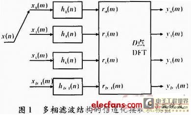
Among them, hk(m) is decomposed from the high-order low-pass filter prototype h(n); h(n) is designed according to the bandwidth of each channel, and h(n) and hk(n) satisfy the relationship hk(n)=h(k+nD), k=0, 1, ..., D-1. In practice, D is often selected as the Nth power of 2 so that the FFT algorithm can be used instead of DFT.
Assume that the number of channels is D and the order of the prototype low-pass filter is N. When each channel outputs one data, the amount of multiplication required by the channelized receiver with a polyphase filtering structure is
S=D×(N/D)+(D/2)×log2D (1)
It can be seen from calculations that the amount of calculation of this type of receiver is much smaller than that of a channelized receiver with a traditional structure, and it has higher efficiency in practical applications.
2 Radar signal detection technology based on polyphase filter structure
With the development of signal generation and processing technology, a radar can often generate a variety of different waveforms as needed. In addition, the modern radar signal environment is becoming increasingly complex, and the signal form is changing. Multiple signals may appear at the same time. By using the multiphase filtering channelization method, the signals that overlap in the time domain but do not overlap in the frequency domain are divided into various sub-channels, which can realize the detection of such signals. The schematic diagram of the channel division form is shown in Figure 2.
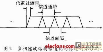
As can be seen from Figure 2, a specific channel stopband attenuation band is designed at the channel overlap, and adjacent channels must have an overlapping area, which can be achieved by setting the bandwidth and transition band of the filter. However, this design method will cause the output of a narrowband signal to span one or more output channels. This situation often occurs when analyzing arbitrary bandwidth and arbitrary center frequency spectrum, so a certain determination method must be used to detect the signal.
For signals that appear in the channel at the same time, it means that the arrival time of the signals is the same. This may be several independent signals that arrive at the same time, or it may be a narrowband signal that is output in two channels at the same time. If the signals appear in non-adjacent channels, they are considered to be several independent signals that arrive at the same time; if the signals appear in two adjacent channels, they are considered to be a narrowband signal that is output in two adjacent channels at the same time. There are two ways to distinguish such signals: when the signal amplitudes of two adjacent channels differ greatly, the signal output channel with a larger amplitude is taken as the channel where the real signal is located; when the signal amplitudes of two adjacent channels are similar, the method of averaging the center frequencies of the two channels can be used, that is, taking 1/2 of the sum of the center frequencies of the two channels. At this time, the frequency measurement error is 1/2 of the channel bandwidth. As long as the error is within the allowable range, this method is feasible.
For signals that appear in different channels at different times, it means that the arrival time of the signals is different. This may be several independent signals or a broadband linear frequency modulation signal that spans several channels. If it is a single broadband linear frequency modulation signal, let its initial frequency be f0; the frequency modulation slope be μ; it arrives at time t0, the bandwidth of each subchannel is B; the center frequency of the i-th channel is fi, then the end time of this signal in the i-th channel is

Because fi+1-fi=B, in the ideal case, that is, when the filter is an ideal filter, ton=toff, which means that the broadband linear frequency modulation signal will appear in each sub-channel in chronological order. However, in general, the filter is not an ideal rectangle, but has a transition band. The size of the transition band is related to the specific design of the filter, which is set to △B here. Due to the influence of the transition band, the signal will not appear in each sub-channel in strict chronological order. The time domain of the signal appearing in the sub-channel will have overlapping parts, and the overlapping time △t≈△B/μ. Therefore, if |ton-toff|<△t is satisfied, it can be considered to appear in each channel in chronological order.
From the above analysis, we can see that if we want to judge that the signal is a single broadband linear frequency modulation signal, two conditions must be met: first, the signal should appear in each adjacent sub-channel in time sequence; second, the amplitude of each sub-channel must be similar. If the arrival time is discontinuous or the amplitude is significantly different, they are considered to be two independent signals.
3. Simulation of radar signal detection with polyphase filter structure
In the simulation, the sampling rate is set to 200 MHz, the number of channels is 16, and the effective signal frequency range is -100 to 100 MHz, so the bandwidth of each channel is 12.5 MHz. Note that there will be a certain overlap between two adjacent channels. This design can ensure that the frequency point will not be lost, but it will also have a certain impact on the detection of the signal.
FIG3 shows the time domain envelope of 8 channels in the positive frequency domain of the channelized receiver with a polyphase filtering structure, and the corresponding FIG4 is the spectrum analysis of each channel.
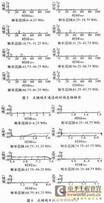
The envelope in Figure 3 is not the original envelope, because the frequency domain of this signal occupies 3 output channels, and the output is output in chronological order, first outputting the envelope of channel 3, then channel 4, and finally channel 5. The corresponding output spectrum also occupies 3 channels, and the passband width of each channel is 12.5 MHz. It can be seen from Figure 4 that the parameter settings of the signal frequency domain output and the input signal are consistent. Figures 3 and 4 are the signal detection results under ideal conditions, and the signal is not in the transition zone where the channels overlap.
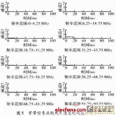
The starting frequency of the narrowband signal is selected as 33.5 MHz, the bandwidth is 100 kHz, and the time domain envelope of the signal is shown in Figure 5. At this time, there are signal outputs in channels 3 and 4, but the signal amplitude in channel 4 is significantly greater than that in channel 3. At this time, it is considered that the real channel where the signal is located is channel 4.
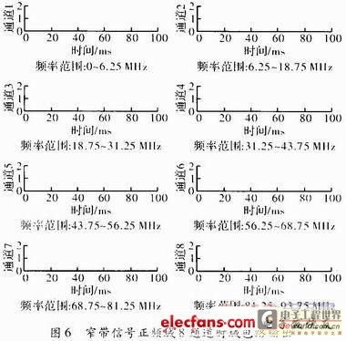
If the signal amplitudes appearing in two adjacent channels are similar, assuming that the starting frequency of the added signal is 31.5 MHz and the bandwidth is 100 kHz, the time domain envelope of the signal is shown in Figure 6. At this time, two signals with similar amplitudes appear in channels 3 and 4, and the above method cannot be used to determine the channel where the signal actually exists. At this time, the method of taking the average of the center frequencies of the two channels can be used to assume that the frequency of the measured signal is approximately 31.25 MHz, and the frequency measurement error is 0.25 MHz. Using this method to estimate the frequency will inevitably produce a certain frequency measurement error, but it is also feasible to a certain extent.
When the signal is in the form of a single broadband linear frequency modulation signal, the signal bandwidth is greater than the bandwidth of a single subchannel. Ideally, the signal will appear in each subchannel in chronological order. Considering the transition band in the actual filter, the signals appearing in each subchannel will overlap in the time domain, and the size of the overlap depends on the design of the filter transition band. The form in which the linear frequency modulation signal appears in the channel is shown in Figures 3 and 4. It should be noted that only when the signal amplitudes in each subchannel are similar and appear in chronological order can the signal be considered a linear frequency modulation signal.
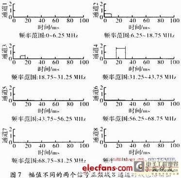
If the signals only appear in time sequence but the amplitudes differ greatly, they are considered to be two signals that arrive in time sequence. As shown in Figure 7, the signal is output on channels 2, 3, and 4. The amplitudes of the first two channels are the same and continuous in time. Although the signal of channel 4 appears after channel 3, its amplitude is significantly greater than the signals appearing in the first two channels. At this time, the signals of channels 2 and 3 are considered to be a linear frequency modulation signal across two channels, while channel 4 is another linear frequency modulation signal.
If the signal amplitudes are similar but not continuous in time, they are also considered to be two signals of the same strength that appear at different times. As shown in Figure 8, the signal is output on channels 2, 3, and 4 and has similar amplitudes. The first two channels are continuous in time, and although the amplitude of the 4-channel signal is the same as that of channels 2 and 3, it appears discontinuously in time. At this time, it is considered that the signal of channels 2 and 3 is a linear frequency modulation signal across two channels, while channel 4 is a linear frequency modulation signal that arrives at another time.
4 Conclusion
From the above research and analysis, it can be concluded that the channelization of the multiphase filter structure is fast and effective for detecting the signal type. Although the overlapping part of the channel will have a certain impact on the measurement of the time-frequency parameters of the signal, if it is judged according to the criteria described above, it can basically meet the requirements for the frugal detection of radar signals. The signal detection method of the digital channelized receiver based on the multiphase filter structure studied in this paper has the advantages of small amount of calculation and convenient real-time processing of system hardware, which has certain significance in engineering implementation.
Previous article:Modem principle analysis
Next article:High-Side Current Sense Amplifier Simplifies Current Monitoring and Control
- Popular Resources
- Popular amplifiers
- High signal-to-noise ratio MEMS microphone drives artificial intelligence interaction
- Advantages of using a differential-to-single-ended RF amplifier in a transmit signal chain design
- ON Semiconductor CEO Appears at Munich Electronica Show and Launches Treo Platform
- ON Semiconductor Launches Industry-Leading Analog and Mixed-Signal Platform
- Analog Devices ADAQ7767-1 μModule DAQ Solution for Rapid Development of Precision Data Acquisition Systems Now Available at Mouser
- Domestic high-precision, high-speed ADC chips are on the rise
- Microcontrollers that combine Hi-Fi, intelligence and USB multi-channel features – ushering in a new era of digital audio
- Using capacitive PGA, Naxin Micro launches high-precision multi-channel 24/16-bit Δ-Σ ADC
- Fully Differential Amplifier Provides High Voltage, Low Noise Signals for Precision Data Acquisition Signal Chain
- Innolux's intelligent steer-by-wire solution makes cars smarter and safer
- 8051 MCU - Parity Check
- How to efficiently balance the sensitivity of tactile sensing interfaces
- What should I do if the servo motor shakes? What causes the servo motor to shake quickly?
- 【Brushless Motor】Analysis of three-phase BLDC motor and sharing of two popular development boards
- Midea Industrial Technology's subsidiaries Clou Electronics and Hekang New Energy jointly appeared at the Munich Battery Energy Storage Exhibition and Solar Energy Exhibition
- Guoxin Sichen | Application of ferroelectric memory PB85RS2MC in power battery management, with a capacity of 2M
- Analysis of common faults of frequency converter
- In a head-on competition with Qualcomm, what kind of cockpit products has Intel come up with?
- Dalian Rongke's all-vanadium liquid flow battery energy storage equipment industrialization project has entered the sprint stage before production
- Allegro MicroSystems Introduces Advanced Magnetic and Inductive Position Sensing Solutions at Electronica 2024
- Car key in the left hand, liveness detection radar in the right hand, UWB is imperative for cars!
- After a decade of rapid development, domestic CIS has entered the market
- Aegis Dagger Battery + Thor EM-i Super Hybrid, Geely New Energy has thrown out two "king bombs"
- A brief discussion on functional safety - fault, error, and failure
- In the smart car 2.0 cycle, these core industry chains are facing major opportunities!
- The United States and Japan are developing new batteries. CATL faces challenges? How should China's new energy battery industry respond?
- Murata launches high-precision 6-axis inertial sensor for automobiles
- Ford patents pre-charge alarm to help save costs and respond to emergencies
- New real-time microcontroller system from Texas Instruments enables smarter processing in automotive and industrial applications
- [RVB2601 Creative Application Development] User Experience 06 -- NTP Timing
- Several necessary steps to learn MCU in depth
- Is the GD32 MCU also out of stock now?
- Share something that gives me a headache (formula)
- Analysis of the working principles of seven triode collector DC circuits
- Op amp output square wave deformation
- 【ST NUCLEO-G071RB Review】——by donatello1996
- Microelectronic Circuits (7th Edition)
- Is there only one company that makes linear optocouplers with feedback?
- Types and Applications of Directional Couplers

 Radar Signal Processing for Autonomous Driving


 京公网安备 11010802033920号