1 Introduction
Greenhouse environmental control is based on the full utilization of natural resources. It obtains the best conditions for crop growth by changing greenhouse environmental factors such as temperature, humidity, light intensity, and carbon dioxide concentration, so as to increase crop yields, improve quality, regulate growth cycles, and improve economic benefits.
Aiming at the problems of poor scalability and low intelligence of the current greenhouse control system, the hardware and software of the greenhouse measurement and control system based on wireless sensor network are designed based on the analysis of the characteristics of wireless sensor network. Sensor nodes and aggregation nodes are designed in hardware, and sensors such as temperature, humidity and light intensity are used to realize the automatic collection of greenhouse environmental parameters. Based on the modular idea, the software realizes the functions of data acquisition, processing and control output. The design has the characteristics of good scalability, strong practicality and easy operation.
2 Architecture of greenhouse measurement and control system
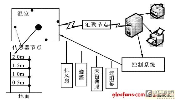
Wireless sensor network (WSN) is a multi-hop self-organizing network system formed by a large number of cheap micro sensor nodes deployed in the monitoring area through wireless communication. It has the advantages of convenient networking and strong flexibility. Its purpose is to collaboratively sense, collect and process the information of the sensed objects in the network coverage area and send it to the observer. Based on the characteristics of wireless sensor networks, the structure of the designed greenhouse measurement and control system is shown in Figure 1.

Figure 1 Structure of greenhouse control system
The sensor nodes collect information such as temperature, humidity, and light intensity from the soil itself or the surrounding environment, complete the given monitoring task, transmit the monitoring data to the control computer for decision-making, and use the actuator to accurately control the fertilizer and water in the soil. The information collected by the sensor network can be used to guide planting to obtain maximum yield, and can also monitor and report the status of crops.
The aggregation node is the intermediary that connects the sensor node and the management node computer in the application environment. It can be used to connect the sensor network with external networks such as the Internet or WWW, realize the communication protocol conversion between protocol stacks, publish the monitoring tasks of the management node, and forward the collected data to the external network.
3 Hardware Design and Control Principle
3.1 Design of sensor nodes
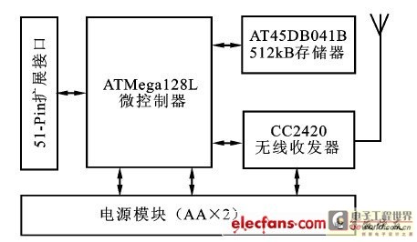
The sensor node is a microcomputer system specially designed for sensor networks. It is the basic unit of wireless sensor networks. It is responsible for sensing and information preprocessing, and responds to the instructions of the monitoring host to send data. It includes five main modules: microcontroller, wireless radio frequency communication, non-volatile Flash memory, expandable I/O interface and power module. The design structure diagram of the sensor node is shown in Figure 2.

Figure 2 Hardware structure of sensor node
The microcontroller unit is the core component of the sensor node, responsible for processing data and coordinating the entire system. Usually, a low-power microcontroller with mixed model processing capabilities is selected. This type of microcontroller generally has universal interfaces such as UART, SPI, and I2C on a single chip; in addition, due to the need to obtain data collected by the sensor, it should also have a multi-channel analog-to-digital converter; finally, the microcontroller must have a power management function so that the node can switch to low-power or even ultra-low-power mode when not working. This design finally selected ATmega128L produced by AT2MEL as the microcontroller unit mainly for the following two reasons: First, the RISC technology used in ATmega128L gives it high computing performance; second, the available open source development software tools for AT2mega128L are mature and the TinyOS operating system (sensor node operating system) supports it well. Therefore, in order to establish a sensor node prototype platform more quickly, ATmega128L is selected as the data processing unit of the node.
As an interface for exchanging information with the outside world, the wireless communication RF module is another important unit of the sensor node. The selection of wireless RF chip involves the chip's data transmission rate, receiving and transmitting power, dormant energy consumption, startup stabilization time, and signal modulation method. Because TinyOS already includes CC2420 driver support, this design uses Chipcon's CC2420 RF chip.
The expansion interface uses the universal 51-pin standard interface of the Mica2 series, which has become the de facto standard interface for interconnecting sensor nodes with sensor modules. The interface consists of two identical parts, which are installed on both sides of the circuit board to achieve module stacking expansion. The sensor node designed according to this interface can directly use most of the sensor modules designed by Crossbow and various research institutions.
Although the ATmega128L microcontroller comes with a 4kB EEPROM data storage area, it is very necessary for sensor nodes to have a relatively larger and permanent data storage area. For example, the automatic update of remote node code and the preservation of node configuration information require more storage space to be applied. In order to implement the log module in the sensor network system status monitoring component, an additional AT45DB041B non-volatile FLASH memory with a size of 512kB is used in the design of the sensor node.
The sensor node is powered by two AA batteries. To reduce costs, the module does not use a dedicated monitoring chip for power-off protection.
3.2 Design of aggregation node
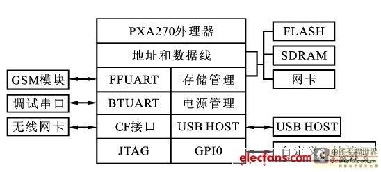
In the greenhouse measurement and control system, the sink node is the bridge for the communication between the sensor network and the management node or other external networks, and plays the role of a gateway in the wireless sensor network. The hardware structure of the sink node is shown in Figure 3.

Figure 3 Hardware structure of the aggregation node
As an ARM processor, PXA270 adopts XScale architecture based on AR2MV5TE, providing powerful processing functions. Compared with PXA25X series processors, PXA270 adds Intel Wireless MMX technology based on XScale micro-architecture, improves the efficiency of multimedia processing, optimizes the power consumption of the processor, and adds new functions designed for mobile terminal devices. Its main features are as follows:
(1) It integrates a rich set of peripheral interfaces, such as USB Host controller, PCMCIA/ SD/ MMC card controller, I2C interface, serial port, real-time clock, SSP serial interface, etc., so the system integration of PXA270 is very high; (2) It has powerful computing power, with the highest main frequency reaching 624MHz; (3) The wireless SpeedStep power management technology enables the system to dynamically adjust the power consumption according to the performance requirements of the CPU, and can dynamically adjust the CPU voltage and frequency to save power. In terms of power management, it supports multiple operating modes. Including a normal operating power mode (running mode) and five low power modes to control power consumption (idle mode, deep idle mode, wait mode, sleep mode, deep sleep mode). The aggregation node implements USB HOST, network, serial port, GSM interface, and a custom 51-pin expansion interface, which is used to connect MICA and MI2CA2 nodes widely used in current wireless sensor networks, or for other functional expansion. The power supply part of the entire system is relatively complex, and CF and GSM are both set up separately.
Other specific hardware implementations are as follows:
FLASH: Using Intel's StrataFlash with fast page read mode, 28F128J3A, the working voltage is 3.3V, the data width is 32Bit, and 4 pieces of Intel's 28F128J3A Flash form a 64MB memory; SDRAM: Using Samsung SDRAM, K4S281632E-TC/L75, 32Bit data width, storage time is 10ns, and two pieces of K4S281632E-TC/L75 form a 64MB SDRAM memory; Network interface: implemented by CS8900A chip, CS8900A can be designed as an ISA bus network card, and this system directly connects it to the processor to realize Ethernet communication, using nCS2 as the chip select enable signal; FFUART: used to connect the GSM module to realize GSM communication function; BTUART: debugging serial port.
In addition, the aggregation node does not need LCD display and keyboard interface. These GPIOs are set by software, and most of them are used to implement a custom 51-pin expansion interface. For other unused GPIOs, they are defined as outputs to reduce power consumption.
4 Software Design and Functional Analysis
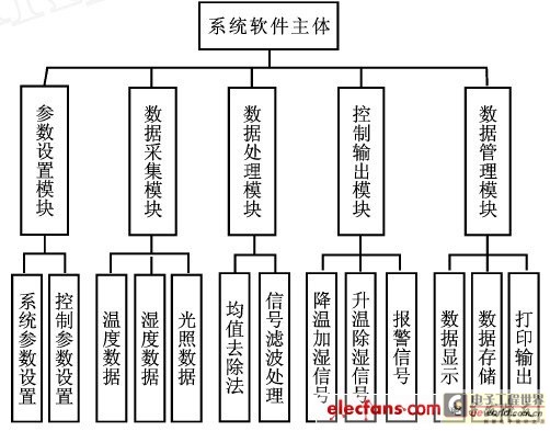
In order to enable operators to intuitively see the various environmental parameter data in the greenhouse and assign tasks, the human-machine interface adopts a friendly graphical interface. The system software consists of five modules: parameter setting module, data acquisition module, data analysis and processing module, control output module, and data management module. The system software structure diagram is shown in Figure 4.

Figure 4 System software structure diagram
(1) Parameter setting module.
When using the greenhouse measurement and control system, the administrator must log in with the account and password. If the password is wrong, access to the system is prohibited. Since different crops have different requirements for environmental parameters at different growth periods, and the same crop has different environmental requirements at different developmental stages, sending environmental parameters as control parameters to the real-time data acquisition control module can better meet the environment required for biological growth. The system parameter setting function is mainly used to set the appropriate values of environmental factors required by humans. The default control parameters that can be sent to the real-time data acquisition control module in the system include temperature, humidity, carbon dioxide concentration, light intensity and other environmental parameters.
(2) Data acquisition module.
The data acquisition module mainly realizes the functions of multi-channel data synchronous acquisition, real-time waveform display and data storage, and displays the real-time changes of environmental factor parameters in the form of dynamic curves or tables.
The task of signal acquisition is to process the voltage signal collected by the sensor through various acquisition channels and then input it into the computer, and finally display it in real time. Whether the collected signal can realize the real signal has a lot to do with the selection of sampling method and the determination of sampling time. This system uses real-time sampling method.
(3) Data processing module.
Data processing is the process of generating information from raw data.
In the system, analog quantities are converted into digital quantities after A/D conversion and sent to the gateway. Before display, alarm and control, this digital quantity must be processed as needed, such as digital filtering, scale conversion, numerical calculation, logical judgment, etc., to meet the different needs of the system.
(4) Control output module.
The control part of this system is mainly to realize the regulation of various environmental factors in the greenhouse. According to the computer data display and alarm signals, operations can be performed on the actuator interface to meet the appropriate growth environment for crops.
(5) Data management module.
The data storage in this system is based on days. The collected 24h real-time monitoring data is stored in the form of files. The stored data files use the data collection date as the file name, and the data collection time and data as the file storage content, which can conveniently meet the file operation. At the same time, it can be analyzed, counted and printed.
5 Conclusion
The greenhouse measurement and control system based on wireless sensor networks has overcome some shortcomings of traditional greenhouses in structure and performance, and also has a certain reference role in the establishment of large-scale intelligent greenhouse groups.
Previous article:Using RF predistortion to achieve power amplifier linearization
Next article:USB radar, build your own missile defense system
Recommended ReadingLatest update time:2024-11-16 19:35


- Popular Resources
- Popular amplifiers
-
 Analysis and Implementation of MAC Protocol for Wireless Sensor Networks (by Yang Zhijun, Xie Xianjie, and Ding Hongwei)
 -
 Introduction to Internet of Things Engineering 2nd Edition (Gongyi Wu)
 -
 西门子S7-12001500 PLC SCL语言编程从入门到精通 (北岛李工)
 -
 Modern Motor Control Technology (Wang Chengyuan, Xia Jiakuan, Sun Yibiao)
- High signal-to-noise ratio MEMS microphone drives artificial intelligence interaction
- Advantages of using a differential-to-single-ended RF amplifier in a transmit signal chain design
- ON Semiconductor CEO Appears at Munich Electronica Show and Launches Treo Platform
- ON Semiconductor Launches Industry-Leading Analog and Mixed-Signal Platform
- Analog Devices ADAQ7767-1 μModule DAQ Solution for Rapid Development of Precision Data Acquisition Systems Now Available at Mouser
- Domestic high-precision, high-speed ADC chips are on the rise
- Microcontrollers that combine Hi-Fi, intelligence and USB multi-channel features – ushering in a new era of digital audio
- Using capacitive PGA, Naxin Micro launches high-precision multi-channel 24/16-bit Δ-Σ ADC
- Fully Differential Amplifier Provides High Voltage, Low Noise Signals for Precision Data Acquisition Signal Chain
- Innolux's intelligent steer-by-wire solution makes cars smarter and safer
- 8051 MCU - Parity Check
- How to efficiently balance the sensitivity of tactile sensing interfaces
- What should I do if the servo motor shakes? What causes the servo motor to shake quickly?
- 【Brushless Motor】Analysis of three-phase BLDC motor and sharing of two popular development boards
- Midea Industrial Technology's subsidiaries Clou Electronics and Hekang New Energy jointly appeared at the Munich Battery Energy Storage Exhibition and Solar Energy Exhibition
- Guoxin Sichen | Application of ferroelectric memory PB85RS2MC in power battery management, with a capacity of 2M
- Analysis of common faults of frequency converter
- In a head-on competition with Qualcomm, what kind of cockpit products has Intel come up with?
- Dalian Rongke's all-vanadium liquid flow battery energy storage equipment industrialization project has entered the sprint stage before production
- Allegro MicroSystems Introduces Advanced Magnetic and Inductive Position Sensing Solutions at Electronica 2024
- Car key in the left hand, liveness detection radar in the right hand, UWB is imperative for cars!
- After a decade of rapid development, domestic CIS has entered the market
- Aegis Dagger Battery + Thor EM-i Super Hybrid, Geely New Energy has thrown out two "king bombs"
- A brief discussion on functional safety - fault, error, and failure
- In the smart car 2.0 cycle, these core industry chains are facing major opportunities!
- The United States and Japan are developing new batteries. CATL faces challenges? How should China's new energy battery industry respond?
- Murata launches high-precision 6-axis inertial sensor for automobiles
- Ford patents pre-charge alarm to help save costs and respond to emergencies
- New real-time microcontroller system from Texas Instruments enables smarter processing in automotive and industrial applications
- SensorTile.Box Entry Mode: Vibration Monitoring to Amuse Your Girlfriend
- 【Gravity:AS7341 Review】+ Design of Color Detector (and Final Report)
- Understanding of MSP430 interrupt mechanism
- Mobile Operation SoC Interface IP Component Design.pdf
- About encryption on products
- [phyBOARD-i.MX 8M Plus Development Board] Evaluation 4: Controlling LED on and off with files in the system root directory
- I wish you all a happy Children's Day! Take a look at the principle of a toy while your child is in kindergarten
- TIP35/36CW VS TIP35/36C
- Has anyone used the MC2-CO-14 carbon monoxide sensor? I have a question.
- [Synopsys IP Resources] EDA on the cloud makes chip innovation "fast, accurate and stable"

 Analysis and Implementation of MAC Protocol for Wireless Sensor Networks (by Yang Zhijun, Xie Xianjie, and Ding Hongwei)


 京公网安备 11010802033920号