Analysis of CAN Scheduling Theory and Practice
Whether messages in the CAN bus can be delivered on time is an important indicator related to system safety and other issues, which must be verified through scheduling analysis. This article introduces the new research results of CAN scheduling theory, as well as its guiding significance for engineering applications and its implementation difficulties. It is divided into four parts: Tindell's analysis method and Davis's improvement; the author's simplification of Davis's algorithm; some results of worst response time analysis in application; and the difficulties of scheduling analysis in application.
Keywords CAN, scheduling theory, response time, Davis algorithm, Tindell algorithm
Distributed embedded systems are an important development direction of current embedded systems because they can provide stronger performance and save the overall cost of the system. However, since each individual node must be connected to a communication network to work in a coordinated manner, the network becomes a key part. Without the network to provide timely and correct data and commands, the designed system service is out of the question. In the distributed embedded system of automobiles, the current mainstream communication network is the CAN bus. CAN is an event-triggered communication protocol that automatically schedules the transmission of messages based on the priority of the message and the status of the node. Low-priority messages may not be sent in time due to too many high-priority messages occurring at the same time, and high-priority messages may also be lost due to the influence of node status, etc. For the limitations of CAN, please refer to reference [1]. This article mainly discusses the problems of the CAN system from the perspective of scheduling theory. These problems are very relevant to engineering applications and have strong practical significance.
1 Tindell's analysis method and Davis's improvement
In 1994, Tindell [23] first transformed the single-processor task scheduling method into a scheduling method suitable for the CAN bus to obtain the worst-case response time of the message. For safety-related applications, only when the worst-case response time is known accurately can it be reasonable. The implementation of CAN communication on the network goes through two stages: the communication task sends the message to the sending communication controller (CC), and the sending communication controller sends the message to the receiving communication controller. In general, the response time is the time from the occurrence of the event that requires communication to the arrival of the message at the target node, including the processing time in the sending node host, the time from the host to the CC, the arbitration transmission time of the message on the bus, and the processing time from the receiving CC to the host. Once the arbitration-winning message begins to be transmitted, it cannot be terminated, so CAN scheduling is a fixed-priority non-preemptive task scheduling. The parameters used by message m are defined as follows:
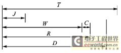
Tm - the interval between events that start communication, i.e., the period;
Jm - the maximum variation in time from the occurrence of an event to the start of message sending to CC, i.e., the jitter;
Cm - the time required to transmit message m on the bus (the maximum value formed by bit stuffing should be taken into account);
Dm - the time limit allowed for transmitting message m, determined by the application;
Rm - the actual worst transmission time;
Wm - the worst waiting time when transmitting message m.
The relationship between them is shown in Figure 1.

Figure 1. Time parameters used for scheduling analysis
Wm consists of two parts: the blocking Bm caused by messages with lower priority than m (whose set is written as lp(m)) being transmitted on the bus, and the interference Im caused by messages with higher priority than m (whose set is written as hp(m)) being transmitted on the bus first. When they take the maximum value, Wm becomes the worst waiting time.

For the convenience of printing and easy understanding, different writing methods are used here, where the ceiling function Ceiling returns the upper limit integer closest to (greater than or equal to) the variable, and τ is 1-bit time. Ceiling ( (Wm+Jk+τ)/Tk) represents the maximum number of times high-priority message k will appear in the Wm period. So:

Wm takes discrete values and appears on both sides of the nonlinear equation (4). Fortunately, it is not difficult to solve. In equation (5), we can use W0m=Bm as the initial value and solve it repeatedly.

Formula (7) means that the worst waiting time has exceeded the time limit and message m cannot be scheduled.
By checking whether the messages are schedulable one by one in order of decreasing priority, it is possible to verify whether the entire communication system is schedulable.
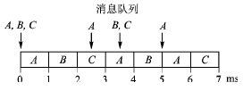
At the 2006 Real-Time Network Conference, Bril, Davis, and others published an article about the loopholes in the Tindell algorithm. Later, they proposed a complete improved algorithm [4]. As a counterexample, message C in Table 1 is schedulable using the Tindell algorithm, with a worst-case response time of 3 ms; but the second transmission of message C has exceeded the time limit, as shown in Figure 2. The Tindell algorithm only considers the first transmission of message C.
Table 1 Counterexamples of Tindell's algorithm


Figure 2 The worst response time for message C is 3.5 ms
In addition, if the cycle of messages B and C is shortened to 3.25 ms, according to the Tindell algorithm, the system is still schedulable because the maximum worst response time is not obtained, but in fact the bus utilization rate has exceeded 100%. The core of Davis's method is to introduce the concept of busy cycle and then calculate the worst value of the response time of each transmission in the busy cycle. See Appendix 1 for details. (See the website of this magazine www.mesnet.com.cn - Editor's note.)
Tindell's pioneering work has a huge impact on subsequent research and applications. Volcano Communications Technology (now Mentor Graphics) developed commercial CAN scheduling analysis software based on this theory. Due to the discovery of the vulnerability, users should check whether the software has a new patch and whether the application completed with it is affected.
2. My Simplification of Davis Algorithm
Davis algorithm first calculates the busy cycle, and then finds the worst waiting time in multiple transmissions of message m during the busy cycle. The calculation can be simplified based on the following considerations:
During the busy cycle, when message m is being transmitted, a high-priority message enters the queue, causing more high-priority messages to be inserted before subsequent messages of m are sent, indicating that there is still a peak in bus demand, which may result in a larger worst-case response time for the subsequent message m.
The worst case is that all high-priority messages enter the queue as soon as message m is sent, that is, the phase leading the first sending slot after message m is sent reaches the maximum.
Therefore, there are two possibilities for calculating the worst response time of message m: use Bm to generate blocking and calculate the worst response time of message m like Tindell; use Cm to generate blocking and calculate the worst response time of the next message m. The queuing time of the next message m is Tm-Jm.
The advantage of the simplified method is that it reduces the number of calculations and thus reduces the workload.
This algorithm is different from the conservative algorithm in Davis algorithm in two aspects: first, it is possible to use Cm to generate blocking, for example, message m is a little earlier than the high-priority message when powering on from sleep mode; second, this algorithm obtains exact rather than conservative results.
Previous article:DTU hardware circuit diagram
Next article:Design of ship monitoring system with CAN bus redundancy
Recommended ReadingLatest update time:2024-11-16 15:59


- Popular Resources
- Popular amplifiers
-
 New Energy Vehicle Control System Inspection and Maintenance (Edited by Bao Pili)
 -
 Detailed explanation of big data technology system: principles, architecture and practice (Dong Xicheng)
 -
 Automotive CAN embedded intrusion detection system based on deep learning
 -
 Lightweight FPGA-based IDS-ECU architecture for automotive CAN networks
- High signal-to-noise ratio MEMS microphone drives artificial intelligence interaction
- Advantages of using a differential-to-single-ended RF amplifier in a transmit signal chain design
- ON Semiconductor CEO Appears at Munich Electronica Show and Launches Treo Platform
- ON Semiconductor Launches Industry-Leading Analog and Mixed-Signal Platform
- Analog Devices ADAQ7767-1 μModule DAQ Solution for Rapid Development of Precision Data Acquisition Systems Now Available at Mouser
- Domestic high-precision, high-speed ADC chips are on the rise
- Microcontrollers that combine Hi-Fi, intelligence and USB multi-channel features – ushering in a new era of digital audio
- Using capacitive PGA, Naxin Micro launches high-precision multi-channel 24/16-bit Δ-Σ ADC
- Fully Differential Amplifier Provides High Voltage, Low Noise Signals for Precision Data Acquisition Signal Chain
- Innolux's intelligent steer-by-wire solution makes cars smarter and safer
- 8051 MCU - Parity Check
- How to efficiently balance the sensitivity of tactile sensing interfaces
- What should I do if the servo motor shakes? What causes the servo motor to shake quickly?
- 【Brushless Motor】Analysis of three-phase BLDC motor and sharing of two popular development boards
- Midea Industrial Technology's subsidiaries Clou Electronics and Hekang New Energy jointly appeared at the Munich Battery Energy Storage Exhibition and Solar Energy Exhibition
- Guoxin Sichen | Application of ferroelectric memory PB85RS2MC in power battery management, with a capacity of 2M
- Analysis of common faults of frequency converter
- In a head-on competition with Qualcomm, what kind of cockpit products has Intel come up with?
- Dalian Rongke's all-vanadium liquid flow battery energy storage equipment industrialization project has entered the sprint stage before production
- Allegro MicroSystems Introduces Advanced Magnetic and Inductive Position Sensing Solutions at Electronica 2024
- Car key in the left hand, liveness detection radar in the right hand, UWB is imperative for cars!
- After a decade of rapid development, domestic CIS has entered the market
- Aegis Dagger Battery + Thor EM-i Super Hybrid, Geely New Energy has thrown out two "king bombs"
- A brief discussion on functional safety - fault, error, and failure
- In the smart car 2.0 cycle, these core industry chains are facing major opportunities!
- The United States and Japan are developing new batteries. CATL faces challenges? How should China's new energy battery industry respond?
- Murata launches high-precision 6-axis inertial sensor for automobiles
- Ford patents pre-charge alarm to help save costs and respond to emergencies
- New real-time microcontroller system from Texas Instruments enables smarter processing in automotive and industrial applications
- MPS Bonus Sharing | Which problem gives you the most headaches in inductor applications?
- Let's take a look at the 3D SmithChart made by experts
- RVB2601 development environment setup and the first program
- 15 "Wanli" Raspberry Pi car - photoelectric encoder learning (forward and reverse judgment)
- A TOF "image" sensor that is worth playing with, VL53L5CX
- ARM immediate number explanation--the difference between LDR and MOV
- i.MX283 latest virtual machine system guide
- TI C5000 compiler error message list
- TI Award-winning Live Broadcast: Talking about "packaged antenna" smart millimeter wave sensors, even novices can handle industrial robots
- The voltage of the TPS73033 buck chip drops to 0.7V after the load is connected

 New Energy Vehicle Control System Inspection and Maintenance (Edited by Bao Pili)


 京公网安备 11010802033920号