O Introduction
PROFIBUS-DP fieldbus is widely used in manufacturing automation, process industry automation and building automation industries due to its advantages such as high speed and low cost. Its physical layer data transmission relies on RS-485 interface. RS-485 interface is a serial communication interface widely used in the industrial field. It can transmit signals in shielded twisted pair in a "differential" manner, so it has good anti-common mode interference capability and the communication distance can reach kilometers. PROFIBUSDP bus signals can also be transmitted using shielded twisted pair. The theoretical transmission distance is 1200 meters when the data rate is 9.6 kbps and 100 meters when the baud rate is 12: Mbps. However, due to the complexity of industrial field conditions, various interferences are superimposed on each other, and the RS-485 standard stipulates that a single-segment network can support up to 32 nodes (standard load). Therefore, it is necessary to use a relay device to transmit the signal to the remote device more accurately and completely. Compared with other transmission media, optical fiber has the advantages of wide bandwidth, low loss, electromagnetic radiation shielding, and light weight. Therefore, using optoelectronic transceivers to realize the conversion between two-wire DP (RS-485) differential signal data and optical signals can effectively improve the signal transmission distance and transmission quality, thereby improving the reliability and stability of the system.
1 Configuration principle of optoelectronic transceiver module
The configuration of the use of this optoelectronic transceiver module is shown in Figure 1. From the physical layer, the original network segment is divided into two segments by the optical fiber. At this time, the transceiver should be regarded as the end of the bus of the corresponding segment. Therefore, a terminal matching resistor is built into the transceiver by default to match the input impedance of the load end with the characteristic impedance of the transmission line, thereby achieving the purpose of eliminating the signal reflection at the load end. Each optoelectronic transceiver occupies a node in electrical performance, so each bus segment can carry up to 30 standard RS-485 load devices.

2 Overall design plan
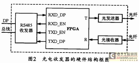
Figure 2 shows the hardware structure block diagram of the optoelectronic transceiver. The design scheme is generally composed of the DP bus data transceiver part, the optical fiber data transceiver part and the data transmission direction control part. As the main controller, FPGA is responsible for controlling the direction of data transmission, detecting the baud rate and data exchange functions. The power supply part uses isolated DC/DC to reduce the influence of external circuits. The RS-485 transceiver of the DP bus on the electrical side can be selected from SN75HVD06D, which can support a data rate of 10 Mbps; while the data receiver and transmitter on the optical side can be selected from AVAGO's optical transmitter HFBR-14x4Z and optical receiver HFBR-24x2Z. When driven by 50mA current, their 62.5/125μm multimode optical fiber transmission distance can reach 2 km. The FPGA chip uses ALTERA's Cvclone series chip EPlC3T144C8N, which has 2910 LE units, 1 PLL and 144 IO pins, and has a high cost performance.

3 FPGA Logic Design
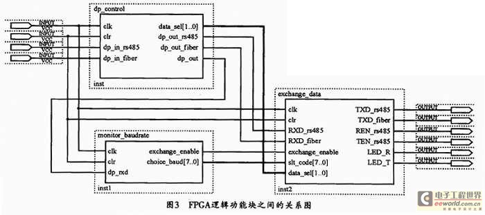
FPGA includes three logical function blocks, namely, data transmission direction detection function block, baud rate detection function block, and data exchange function block. Their electrical and optical ends are in receiving state by default. The data transmission direction detection function block is used to determine which port receives data first, and then outputs the port data to the baud rate detection function block to detect its data baud rate. The data exchange function block can switch the receiving and transmitting state of the RS-485 transceiver according to the determined data transmission direction and baud rate, and finally realize the photoelectric conversion transmission of data. The relationship between the three logical function blocks is shown in Figure 3.

3.1 Data transmission direction detection logic
The transmission of PROHBUS-DP bus protocol relies on RS-485 interface, so when the bus is idle, the pull-up and pull-down resistors at the front end of RS-485 interface can ensure that the level on the bus is "1", and RS-485 transceiver generally defaults to receiving state. Since RS-485 data transmission is half-duplex, at the same time. The data transmission direction on the line is unidirectional, and the start bit of the transmission data byte is low level. In this way, the data transmission direction can be judged from the electrical end to the optical end, or from the optical end to the electrical end according to the order of the low level of the data received by the electrical end and the data received by the optical end. In order to avoid burrs caused by interference on the line or the characteristics of data transceiver components, the received electrical end data and optical end data can be filtered and de-jittered first. Figure 4 shows the data transmission direction detection flow chart.

3.2 Baud rate detection logic
First, the data selected and output by the data transmission direction detection function block should be filtered. Different baud rates use corresponding clocks to sample the filtered data. If 16 consecutive "1"s are sampled, it means that the bus is currently in an idle state. The next low level is the start bit of the data byte, and then the data can be received. After a byte (8 bits) of data is received, it can be determined whether the received data is a keyword (the keyword is the start delimiter SDx of the PROFIBUS-DP bus protocol data frame). If a certain baud rate finds the keyword three times in a row, the number of times the other baud rates have found the keyword in a row will be cleared. And the previously determined baud rate bit will be cleared. When the baud rate finds the keyword six times in a row, it means that a new baud rate has been found. At this time, the baud rate just found can be determined as the current system communication rate, and the corresponding flag position is set to 1.
3.3 Data Exchange Logic
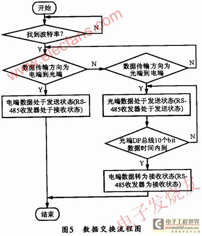
After the data transmission direction and baud rate are determined, the data exchange between the electrical end and the optical end can be carried out. When the data transmission direction is from the electrical end to the optical end, the RS-485 transceiver on the electrical end is in the receiving state, and the data is sent from the electrical end to the optical end line via the optical transmitter; when the data transmission direction is from the optical end to the electrical end, after the start bit data "0" is sent, the RS-485 transceiver on the electrical end can be changed to the sending state, and after 10 bit times of the current communication baud rate, the RS-485 transceiver is changed to the receiving state and waits for receiving new data. Figure 5 shows the data exchange flow chart.

4 Conclusion
The innovation of this design is that it uses FPGA hardware to realize the conversion between photoelectric signals, can adapt to baud rate changes, and automatically detect baud rate changes. It can support all baud rates specified by the PROFIBUS-DP protocol and forward data without error packets. Compared with general RS-485 relay equipment, it not only has a great improvement in transmission distance and bus load capacity. It also has outstanding advantages in anti-interference and communication stability, and can be used in various PROFIBUS-DP bus industrial sites.
Previous article:Design of elevator call system based on CAN bus
Next article:Multi-channel serial data acquisition system based on PCI bus module
Recommended ReadingLatest update time:2024-11-17 01:29

- Popular Resources
- Popular amplifiers
- High signal-to-noise ratio MEMS microphone drives artificial intelligence interaction
- Advantages of using a differential-to-single-ended RF amplifier in a transmit signal chain design
- ON Semiconductor CEO Appears at Munich Electronica Show and Launches Treo Platform
- ON Semiconductor Launches Industry-Leading Analog and Mixed-Signal Platform
- Analog Devices ADAQ7767-1 μModule DAQ Solution for Rapid Development of Precision Data Acquisition Systems Now Available at Mouser
- Domestic high-precision, high-speed ADC chips are on the rise
- Microcontrollers that combine Hi-Fi, intelligence and USB multi-channel features – ushering in a new era of digital audio
- Using capacitive PGA, Naxin Micro launches high-precision multi-channel 24/16-bit Δ-Σ ADC
- Fully Differential Amplifier Provides High Voltage, Low Noise Signals for Precision Data Acquisition Signal Chain
- Innolux's intelligent steer-by-wire solution makes cars smarter and safer
- 8051 MCU - Parity Check
- How to efficiently balance the sensitivity of tactile sensing interfaces
- What should I do if the servo motor shakes? What causes the servo motor to shake quickly?
- 【Brushless Motor】Analysis of three-phase BLDC motor and sharing of two popular development boards
- Midea Industrial Technology's subsidiaries Clou Electronics and Hekang New Energy jointly appeared at the Munich Battery Energy Storage Exhibition and Solar Energy Exhibition
- Guoxin Sichen | Application of ferroelectric memory PB85RS2MC in power battery management, with a capacity of 2M
- Analysis of common faults of frequency converter
- In a head-on competition with Qualcomm, what kind of cockpit products has Intel come up with?
- Dalian Rongke's all-vanadium liquid flow battery energy storage equipment industrialization project has entered the sprint stage before production
- Allegro MicroSystems Introduces Advanced Magnetic and Inductive Position Sensing Solutions at Electronica 2024
- Car key in the left hand, liveness detection radar in the right hand, UWB is imperative for cars!
- After a decade of rapid development, domestic CIS has entered the market
- Aegis Dagger Battery + Thor EM-i Super Hybrid, Geely New Energy has thrown out two "king bombs"
- A brief discussion on functional safety - fault, error, and failure
- In the smart car 2.0 cycle, these core industry chains are facing major opportunities!
- Rambus Launches Industry's First HBM 4 Controller IP: What Are the Technical Details Behind It?
- The United States and Japan are developing new batteries. CATL faces challenges? How should China's new energy battery industry respond?
- Murata launches high-precision 6-axis inertial sensor for automobiles
- Ford patents pre-charge alarm to help save costs and respond to emergencies
- Hobbylord Bumblebee ST550 Foldable Carbon Fiber Quadcopter
- PCB manufacturing experience summary (1)
- MM32F103 BUG reminder to avoid falling into the pit 2? Please answer
- Maybe I'm the only one who has messed up a development board with code.
- Teach you how to implement serial port burning of TMS320F28035
- How to enable traditional surface power supply to use type-c PD fast charging charger?
- How to use Cadence Allegro to form a dot-shaped copper layer
- What is the manufacturing process level of a microcontroller like STM32?
- LM27762 Charge Pump with Integrated Positive and Negative LDO
- Transfer a video "There is a kind of beauty called mathematics"

 Learn S7-300400 PLC with me (2nd Edition)


 京公网安备 11010802033920号