1 Basic Principles of Brushless DC Motor
The brushless DC motor system shown in Figure 1 is used to illustrate the basic working principle of the brushless DC motor. The stator winding of the motor is a three-phase star connection. The position sensor is coaxial with the motor rotor. The control circuit generates a drive signal after performing a logical transformation on the position signal. The drive signal is amplified by the drive circuit and controls the power switch tube of the inverter, so that each phase winding of the motor works in a certain order. When the rotor rotates to the position shown in Figure 2 (a), the signal output by the rotor position sensor drives the inverter after the control circuit logic transformation, so that VI1 and VI6 (see Figure 1) are turned on, and the A and B two-phase windings are energized. The current flows out from the positive pole of the power supply, flows into the A phase winding through VI1, and then flows out from the B phase winding and returns to the negative pole of the power supply through VI6.
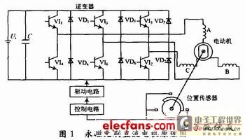
The magnetomotive force Fa generated by the armature winding in space is shown in Figure 2(a). At this time, the stator and rotor magnetic fields interact with each other, causing the rotor of the motor to rotate clockwise.
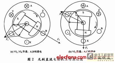
When the rotor rotates 60° electrical angle in space and reaches the position shown in Figure 2(b), VI1 and VI2 are turned on, causing the rotor of the motor to continue to rotate clockwise.
Every time the rotor rotates 60° in space, the inverter switch switches once, and the conduction logic of the power switch tube is VI1, VI6→VI1, VI2→VI3, VI2→VI3, VI4→VI5, VI4→VI5, VI6→VI1, VI6. In this cycle, the rotor is always subjected to the clockwise electromagnetic torque and rotates continuously in the clockwise direction.
In the 60° electrical angle range from Figure 2(a) to Figure 2(b), the rotor magnetic field rotates continuously in the clockwise direction, while the stator composite magnetic field does not rotate continuously in space, but is a jumping rotating magnetic field with a step of 60° electrical angle. Every time the rotor rotates 60° electrical angle in space, the stator winding undergoes a commutation, and the state of the stator composite magnetic field changes. It can be seen that the motor has six states, each state has two phases turned on, and the conduction time of each phase winding is the time for the rotor to rotate 120° electrical angle. This working mode is called two-phase conduction star three-phase six-state.
As long as the controllable transistors connected to the output terminals of each phase are turned on and off in an appropriate order according to the different positions of the magnetic poles, and the magnetic motive force generated by the rotor coil is always kept ahead of the magnetic motive force of the magnetic poles by a certain electrical angle, the motor can generate electromagnetic torque in a certain direction and run stably. It can be seen that the forward and reverse rotation of the motor can be achieved by changing the conduction order of the power transistors with the help of logic circuits.
2 Software Design
2.1 Main program flow chart
In the process of motor design, the most important thing is to solve the problem of a large number of curves and charts. This routine uses interpolation and fitting methods to process a large number of formulas and curves. Although it will produce a small error, it is convenient and fast to use and saves time. The main program flow chart is shown in Figure 3.
2.2 Programming Design Interface
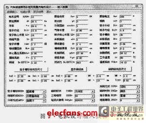
The VB 6.0 programming language is used to implement the motor design visualization interface, which can quickly and accurately obtain the required data, save time and improve work efficiency, as shown in Figure 4.
2.3 Programming
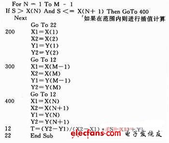
In addition to the calculation formula, some charts and curves used in motor design need to be calculated by interpolation method if there is no original formula. In essence, the straight line segment between two points near the interpolation point x is used to replace the curve segment, and the function on the curve corresponding to x is approximately replaced by the corresponding function on this straight line segment. Some program codes are as follows:

3 Experimental Results
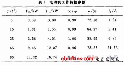
This example is a three-phase brushless DC motor with a power of 4 kW, a rated voltage of 208 V, a rated frequency of 26.5 Hz, and a pole pair number of 3. The motor operating characteristics are shown in Table 1 based on the calculation.
4 Conclusion
This paper uses modern motor design methods to design a prototype of a vehicle retarder motor. The performance indicators meet the technical requirements. Through the comparative analysis of experimental data and design results, it is concluded that the feasibility and efficiency of using brushless DC motors on retarders are achieved. The purpose of lightweight and miniaturization of automotive retarders is achieved, which shows that the application of brushless DC motors in automotive retarders is a future development trend.
Previous article:DS1876 SFP Controller Quick Reference Design
Next article:Application of ESP904 in ROV control system
Recommended ReadingLatest update time:2024-11-17 02:36

- Popular Resources
- Popular amplifiers
- High signal-to-noise ratio MEMS microphone drives artificial intelligence interaction
- Advantages of using a differential-to-single-ended RF amplifier in a transmit signal chain design
- ON Semiconductor CEO Appears at Munich Electronica Show and Launches Treo Platform
- ON Semiconductor Launches Industry-Leading Analog and Mixed-Signal Platform
- Analog Devices ADAQ7767-1 μModule DAQ Solution for Rapid Development of Precision Data Acquisition Systems Now Available at Mouser
- Domestic high-precision, high-speed ADC chips are on the rise
- Microcontrollers that combine Hi-Fi, intelligence and USB multi-channel features – ushering in a new era of digital audio
- Using capacitive PGA, Naxin Micro launches high-precision multi-channel 24/16-bit Δ-Σ ADC
- Fully Differential Amplifier Provides High Voltage, Low Noise Signals for Precision Data Acquisition Signal Chain
- Innolux's intelligent steer-by-wire solution makes cars smarter and safer
- 8051 MCU - Parity Check
- How to efficiently balance the sensitivity of tactile sensing interfaces
- What should I do if the servo motor shakes? What causes the servo motor to shake quickly?
- 【Brushless Motor】Analysis of three-phase BLDC motor and sharing of two popular development boards
- Midea Industrial Technology's subsidiaries Clou Electronics and Hekang New Energy jointly appeared at the Munich Battery Energy Storage Exhibition and Solar Energy Exhibition
- Guoxin Sichen | Application of ferroelectric memory PB85RS2MC in power battery management, with a capacity of 2M
- Analysis of common faults of frequency converter
- In a head-on competition with Qualcomm, what kind of cockpit products has Intel come up with?
- Dalian Rongke's all-vanadium liquid flow battery energy storage equipment industrialization project has entered the sprint stage before production
- Allegro MicroSystems Introduces Advanced Magnetic and Inductive Position Sensing Solutions at Electronica 2024
- Car key in the left hand, liveness detection radar in the right hand, UWB is imperative for cars!
- After a decade of rapid development, domestic CIS has entered the market
- Aegis Dagger Battery + Thor EM-i Super Hybrid, Geely New Energy has thrown out two "king bombs"
- A brief discussion on functional safety - fault, error, and failure
- In the smart car 2.0 cycle, these core industry chains are facing major opportunities!
- Rambus Launches Industry's First HBM 4 Controller IP: What Are the Technical Details Behind It?
- The United States and Japan are developing new batteries. CATL faces challenges? How should China's new energy battery industry respond?
- Murata launches high-precision 6-axis inertial sensor for automobiles
- Ford patents pre-charge alarm to help save costs and respond to emergencies
- [Flower carving DIY] Interesting and fun music visualization series project (28) - LED table tennis lamp
- Design of overvoltage protection circuit in TI chip Buck-Boost circuit
- Sharing the OS transplantation and application of Lingdongwei MM32 MCU--Based on I2C interface control of AMetal platform
- What do you think of the official open source of Huawei's Ark Compiler?
- [New version of Zhongke Bluexun AB32VG1 RISC-V development board] - 5: Enhanced version of Blink
- Current Status and Future Development of Satellite Mobile Communications
- Intelligently Connected World—Application of Internet of Vehicles and Future Development of Digitalization
- Motor drive circuit design 1
- Free Review - Topmicro Intelligent Display Module (5) Touch Screen
- How to deal with the acidic wastewater from acid salt spray testing of metal electronic products and devices?

 100 Examples of Microcontroller C Language Applications (with CD-ROM, 3rd Edition) (Wang Huiliang, Wang Dongfeng, Dong Guanqiang)


 京公网安备 11010802033920号