Abstract: Most automotive electronic systems require monitoring circuits to monitor failure tolerance and safety. The MAX16997/MAX16998 watchdog timers are ideal for such monitoring needs. They detect periodic pulses generated by the microcontroller (µC) under normal working conditions. Once a circuit or µC failure is detected, it will immediately switch to the backup/redundant system and adopt a "limp home" control strategy to prevent the car from breaking down midway, providing a car failure protection measure.
In automotive design, more and more electronic systems are gradually replacing mechanical functions—from engine timing control to brake and steering wheel control—and electronic systems are relatively prone to failure, which requires careful consideration of system safety and ensuring that the system has a high fault tolerance. Drivers or passengers should not be put in danger in the event of a single point of failure, at least the car can be "limped" off the road or to the nearest repair station. When an electronic device fails, in order to ensure the safe driving of the car, it is necessary to use monitoring circuits to open backup circuits and safely take over system operations.
In the days of purely mechanical cars, the engine ignited the air-fuel mixture in response to a mechanically generated signal. A mechanical distributor selected the appropriate spark plug and passed the signal along the line. The brake system transmitted the pressure applied to the pedal through the brake shaft, brake master cylinder, and hydraulic pipes to the brake calipers. The clutch and throttle were simply controlled by a steel cable connected to the pedal. The steering wheel controlled the angle of the wheels through a metal steering wheel, steering shaft, steering gear box, and steering transmission. The engine control was also different from the highly reliable electronic control unit (ECU) we use today. It did not have computer-assisted brakes, clutches, throttles, or steering systems. Of course, there was no need to consider the failure of the µC or the short circuit of the control unit. There were only 99 mechanical devices that could fail. However, because people trusted the reliability of mechanical equipment, they rarely considered system backup or fault tolerance. Of course, if a device in the system failed, it could easily cause danger, and even if it did not cause danger, the car would be stranded at the accident site and had to be towed to a repair center by a tow truck.
To improve the comfort and convenience of driving, car manufacturers need to provide cars with electronic equipment to achieve higher efficiency, a cleaner environment and higher driving safety. Early ECUs could only stop running when a fault occurred, especially when the operation of the electronic device depended on the µC. It was unacceptable to both users and manufacturers if there was no backup plan to avoid life-threatening accidents when the µC failed; at least a backup system was required in the design to drive the car to the nearest repair station. As a result, people's attention to fault tolerance has also increased rapidly. According to actual needs, many ECUs have begun to be equipped with a "limp home" management mode.
"Limp Home" Mode
The "limp home" mode refers to a redundant function within the ECU. In terms of physical architecture, this is a completely independent part of the analog circuit that can be turned on from standby mode to enter a fail-safe state. This mode allows the car to leave the road in the event of an electronic system failure. Although the original driving performance cannot be maintained, safety can be ensured.
The new generation of engine ECUs are equipped with monitoring devices, such as watchdog timers, to test whether the ECU is operating normally. Once an abnormality is detected, such as a failure of the electronic device or µC (software operation failure), the monitoring device will start the "limp home" control mode. For example, when the car engine fault light is on, only half of the fuel is injected into the cylinder to the engine. At this time, the engine generates very low heat, but the car can be driven at a moderate speed, with just enough energy to drive the car home or to the nearest car repair center.
Another good example is the "body control computer" in new cars, which controls the window lifts, headlights/taillights, turn signals, windshield wipers, and automatic gear shift control of the car. The monitoring circuit monitors the working condition of the ECU, and in the event of a circuit unit or µC operating failure, it will activate the standby circuit and degrade the driving performance, such as reducing the brightness of the high beam, taillights/brake lights, or only maintaining second gear. Of course, this condition limits the top speed of the car, but the car still remains operational and can be driven safely in "limp home" mode to the repair shop.
Is it bad? No, it's not. If it weren't, you would have been driving at the same speed, which could have resulted in vehicle damage, or you could have been driving nowhere, including to a safe location.
redundancy
The prospect of computer control application is called "electronic control operation". Most mechanical control systems inside and outside the power system have been replaced by electromechanical control. For example, the interconnected ECU electronic control devices have replaced all mechanical units between the steering wheel and the wheels. The position of the steering wheel moved by the driver will be detected and converted into digital electrical signals, which will be transmitted to the intelligent electromechanical transmission device, and finally control the wheel movement.
Electronically controlled brakes also use automotive computers, servo motors or electromechanical brake calipers to replace early units such as brake shafts, master cylinders and brake boosters.
Generally speaking, since failure of the brake or steering system may endanger life, these systems have higher safety requirements and higher fault tolerance requirements.
Engineers have designed backup circuits in these new applications to build complete redundant electronic control and monitoring units. The redundant system should be completely independent of the main control unit in terms of physical structure to ensure that the system always provides effective and safe electronic control units. The ECU monitoring circuit maintains continuous monitoring of the main system and can switch to the backup and redundant system when a failure occurs. The principle of the application of the redundant system is that the probability of multiple control units failing at the same time is much lower than the probability of a single failure point in a single ECU. Therefore, redundant control units can provide additional safety for automotive systems.
Advantages of High Voltage Watchdog
Considering safety issues, automotive electronic systems need monitoring circuits to monitor fault tolerance or safety. The MAX16997/MAX16998 watchdog timers are ideal for meeting such requirements. They detect the periodic pulses generated by the microcontroller (µC) under normal working conditions, detect the failure of the circuit or µC, and immediately switch to the backup/redundant system if a fault occurs.
The MAX16997/MAX16998 feature timeout and windowed watchdog monitoring. The devices include a watchdog trigger input (WDI), an open-drain µC reset output (RESET), and an open-drain redundant system-enable output (ENABLE).
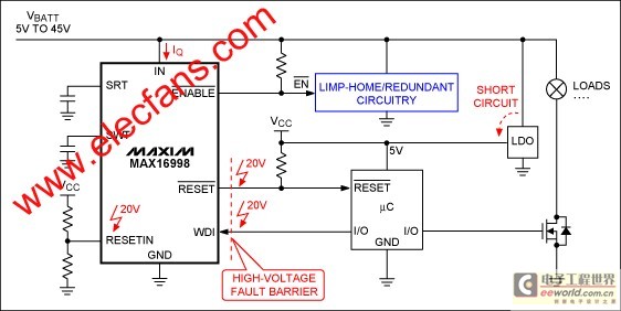
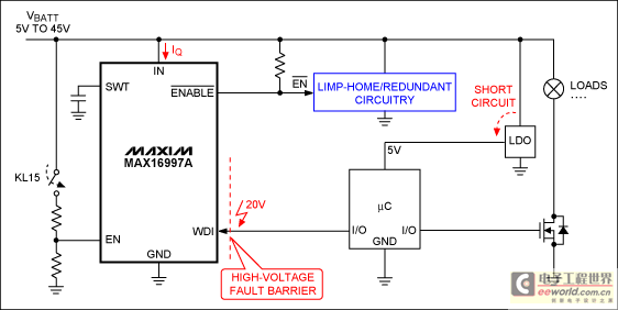
For the MAX16998, the reset threshold can be set by an external resistor divider between a low-voltage supply (e.g., µC supply), an external voltage-monitoring input (RESETIN), and GND (see Figure 1). The MAX16997 can read the state of KL15 (ignition switch) at the enable input (EN) to enable the internal watchdog timer after the vehicle is started (Figure 2). In this case, the watchdog timeout period is extended to eight times the nominal period, leaving enough time for the µC to turn on.

Figure 1. The MAX16998 high-voltage watchdog timer is powered from an independent downstream low-voltage supply (LDO), providing a safety barrier for short-to-battery protection, allowing the device to reliably switch to redundant circuitry under fault conditions.

Figure 2. Like the MAX16998, the MAX16997 can safely switch to redundant circuitry during a fault condition. It also features an active-high enable input (EN) that turns the watchdog timer on or off.
The reset delay (MAX16998) and watchdog timeout can be independently set using external capacitors (placed at the SRT and SWT inputs, respectively). The watchdog window detection can be factory preset to 50% or 75% of the adjustable watchdog period.
The ultra-low 18µA (typ) operating current makes the MAX16997/MAX16998 very important in automotive ECU applications, where these circuits are always on. In addition, these devices are available in a 3mm x 3mm, 8-pin µMAX® package and are guaranteed to operate over the -40°C to +125°C automotive temperature range.
These ICs are powered directly from the 12V car battery and can withstand voltage transients up to 45V (IN and ENABLE pins), whereas typical watchdog timers are powered from a downstream low-voltage supply (e.g., 5V). As a result, the MAX16997/MAX16998 remain operational and safely switch to redundant circuitry (by toggling the ENABLE pin) even when the downstream circuitry is powered off or shorted to ground. To enable these devices to support higher fault tolerance, the devices offer 20V fault tolerance on the RESET, WDI, EN, and RESETIN pins, and can even withstand shorts to the car battery (Figures 1 and 2). As can be seen, these circuits also provide a reliable protection barrier to avoid failures in downstream high-voltage circuits. The backup circuit should be physically independent of the "regular" control circuit and be able to safely switch to the backup mode in the event of a fault.
MAX16997/MAX16998 Timing
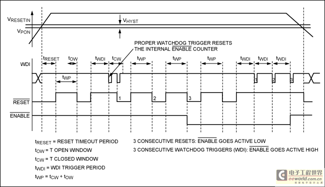
After power-on, when the RESETIN pin voltage (VRESETIN) is higher than the power-on reset threshold (VPON), RESET will remain low for the power-on reset time (tRESET) and then go high. At the same time, the watchdog timer starts timing (tWP). If the WDI trigger signal is not generated within the specified open time window (tOW), RESET will be set low again to reset the µC. If the trigger signal is in the closed window (tCW) or after the watchdog period (tWP) for three consecutive watchdog trigger signals, the ENABLE signal will be set low to switch the system to the redundant circuit. If the WDI trigger signal returns to the open watchdog period window (tWDI) for three consecutive watchdog trigger signals, ENABLE will return to high again and the system will switch to normal operation mode (Figure 3).

Figure 3. MAX16998 timing diagram (windowed watchdog)
Watchdog timeout and window watchdog
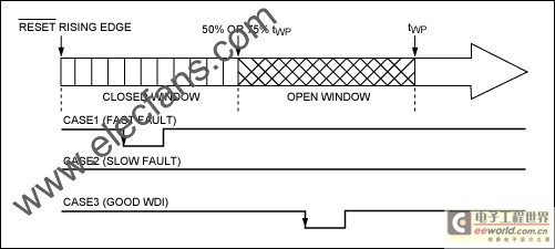
The MAX16997/MAX16998A provide a standard watchdog timeout period, while the MAX16998B/D provide a windowed watchdog function (Figure 4). Depending on the level of safety required by the application, the device type is selected and the watchdog timeout is adjusted to ensure that the timer is cleared within the watchdog timer period, otherwise the device will generate a reset signal. Thus, these watchdogs can be used to detect failure conditions in program execution, such as program execution too slow or a digital clock (e.g., a clock generated by a crystal oscillator) slowing down; while windowed watchdogs ensure that the timer is cleared within a specified time window. Therefore, they can detect some additional faults, such as program execution too fast or clock execution too fast, and can support higher safety levels.

Figure 4. MAX16998 watchdog timer period (window watchdog)
The third case in Figure 4 illustrates the situation where the WDI is triggered within the specified time window; the first case is that the WDI is triggered incorrectly. The signal triggers the WDI too early, resulting in a fault indication. The cause of the fault is that the program runs too fast or the oscillator clock frequency is increased; the second case is also a manifestation of incorrectly triggering the WDI - the watchdog trigger signal output delay is too large, indicating that the program runs too slowly or the oscillator clock frequency slows down.
in conclusion
Fault tolerance and automotive safety have become key factors in automotive electronic design. In order to improve automotive efficiency, improve comfort and reduce risks, it is necessary to efficiently manage the various units of the system: hardware, software, sensors, passive devices and operating units. High-voltage watchdog timers, such as MAX16997/MAX16998, play a key role in achieving this goal.
Previous article:Design considerations for electronic sphygmomanometers
Next article:Si5350 is the most frequency-flexible in-circuit programmable CMOS clock generator
Recommended ReadingLatest update time:2024-11-16 21:35
- High signal-to-noise ratio MEMS microphone drives artificial intelligence interaction
- Advantages of using a differential-to-single-ended RF amplifier in a transmit signal chain design
- ON Semiconductor CEO Appears at Munich Electronica Show and Launches Treo Platform
- ON Semiconductor Launches Industry-Leading Analog and Mixed-Signal Platform
- Analog Devices ADAQ7767-1 μModule DAQ Solution for Rapid Development of Precision Data Acquisition Systems Now Available at Mouser
- Domestic high-precision, high-speed ADC chips are on the rise
- Microcontrollers that combine Hi-Fi, intelligence and USB multi-channel features – ushering in a new era of digital audio
- Using capacitive PGA, Naxin Micro launches high-precision multi-channel 24/16-bit Δ-Σ ADC
- Fully Differential Amplifier Provides High Voltage, Low Noise Signals for Precision Data Acquisition Signal Chain
- Innolux's intelligent steer-by-wire solution makes cars smarter and safer
- 8051 MCU - Parity Check
- How to efficiently balance the sensitivity of tactile sensing interfaces
- What should I do if the servo motor shakes? What causes the servo motor to shake quickly?
- 【Brushless Motor】Analysis of three-phase BLDC motor and sharing of two popular development boards
- Midea Industrial Technology's subsidiaries Clou Electronics and Hekang New Energy jointly appeared at the Munich Battery Energy Storage Exhibition and Solar Energy Exhibition
- Guoxin Sichen | Application of ferroelectric memory PB85RS2MC in power battery management, with a capacity of 2M
- Analysis of common faults of frequency converter
- In a head-on competition with Qualcomm, what kind of cockpit products has Intel come up with?
- Dalian Rongke's all-vanadium liquid flow battery energy storage equipment industrialization project has entered the sprint stage before production
- Allegro MicroSystems Introduces Advanced Magnetic and Inductive Position Sensing Solutions at Electronica 2024
- Car key in the left hand, liveness detection radar in the right hand, UWB is imperative for cars!
- After a decade of rapid development, domestic CIS has entered the market
- Aegis Dagger Battery + Thor EM-i Super Hybrid, Geely New Energy has thrown out two "king bombs"
- A brief discussion on functional safety - fault, error, and failure
- In the smart car 2.0 cycle, these core industry chains are facing major opportunities!
- The United States and Japan are developing new batteries. CATL faces challenges? How should China's new energy battery industry respond?
- Murata launches high-precision 6-axis inertial sensor for automobiles
- Ford patents pre-charge alarm to help save costs and respond to emergencies
- New real-time microcontroller system from Texas Instruments enables smarter processing in automotive and industrial applications
- RF PA circuit design based on gallium nitride (GaN) devices
- [Project source code] NIOS II custom IP core writing basic framework
- What circuit is generally used to achieve the LED light gradually turning on and off function?
- Sugar Glider Part 7: Software Design of the Exercise Reward System for Sugar Glider Based on RSL10
- The magical problem encountered by KICAD
- X-NUCLEO-IKS01A3 Official Technical Data
- AT32F425-Evaluation Report-Serial Port and Waveform Display Host Computer Debugging-09
- There is a car image simulation project for paid consultation, using the Freescale solution
- Take a look at the USB Host microcontroller in gaming peripherals
- What is the component B93 on the circuit board?

 西门子S7-12001500 PLC SCL语言编程从入门到精通 (北岛李工)
 FollowMe Issue 3 - Plant Care Monitor - MicroPython - XiaoESP32C3
 Example interpretation of 51 single chip microcomputer complete learning and application


 京公网安备 11010802033920号