For steady-state circuits excited by non-sinusoidal periodic signals, it is impossible to use the calculation methods of DC circuits or sinusoidal AC circuits for analysis and calculation. Instead, the non-sinusoidal periodic signal excitation must first be decomposed into the sum of sinusoidal components of different frequencies using Fourier series, and then the circuit response under the excitation of each frequency component is calculated separately. Finally, the superposition theorem is used to superimpose the response components to obtain the steady-state response. The main steps of the calculation process can be divided into three steps:
(1) Decompose the given non-sinusoidal periodic excitation source into a Fourier series expression, that is, decompose it into the sum of the DC component and each harmonic component, and determine the required number of harmonic terms based on the convergence of the expansion terms and the required accuracy;
(2) Calculate the circuit response under the excitation of the DC component and the harmonic components of each frequency respectively. The DC component uses the DC circuit analysis method, in which the inductor is short-circuited and the capacitor is open-circuited; for sinusoidal components of different frequencies, the sinusoidal circuit phasor analysis calculation method is used. At this time, it should be noted that the impedance of the circuit changes with the frequency. When calculating each component separately, a corresponding circuit diagram should be made;
(3) Apply the superposition theorem to add the harmonic components of the output response to obtain the total response value. Note that each harmonic response should be expressed as an instantaneous form in the time domain before superposition (because the addition of phasor forms of different frequencies is meaningless).
The following specific examples are used to illustrate the periodic non-sinusoidal steady-state analysis of linear circuits.
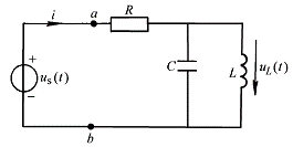
Example 6-2-1 The circuit is shown in Figure 6-2-1. Given
,
,
, power supply voltage
, fundamental angular frequency
, find the current flowing through the resistor
and the voltage across the inductor
.
![]()
![]()
![]()
![]()
![]()
![]()
![]()

Figure 6-2-1
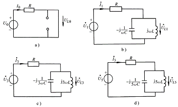
Solution: The excitation voltage source in this problem has been decomposed into harmonic components, so the calculation of each harmonic can be performed directly. For the calculation of the DC component, the method of solving the problem of a general DC circuit can be used to draw the corresponding DC circuit as shown in Figure 6-2-2a. Given
that
![]()
![]()
![]()
For the fundamental wave component
, the corresponding circuit is shown in Figure 6-2-2b,
and
the input impedance of
ab
terminal is:
![]()
![]()

Figure 6-2-2

![]()
Voltage across the inductor:
![]()
That is:
![]() ,
,
![]()
For the third harmonic component, its equivalent circuit is shown in Figure 6-2-2c,
and its input impedance is:
![]()

![]()
Voltage across the inductor:
![]()
That is:
![]() ,
,
![]()
For the fifth harmonic, the equivalent circuit is shown in Figure 6-2-2d, where
the
input impedance of the
ab
terminal is:
![]()

![]()
![]()
Voltage across the inductor:
![]()
That is:
![]() ,
,
![]()
Finally, the current flowing through the resistor is:
![]()
![]()
![]()
![]()
![]()
![]()
From the calculation results, it can be seen that the circuit presents different characteristics for components of different frequencies. When the third harmonic is excited, the input impedance is particularly large, so the current component generated is small, which is due to the proximity to the resonant frequency point of the circuit.
The following discusses the effective value and power of non-sinusoidal periodic signals. The effective value of a periodic signal has been defined as:
![]()
For non-sinusoidal periodic signal current
, it can be expanded into Fourier series:
![]()
![]()
Substituting valid value expressions are:

Expanding the square inside the square root sign gives two types of expressions. One type is the square of the current component with the same frequency, which can be calculated as:
![]()
![]()
![]()
The second type is the product of currents of different frequencies. From the orthogonality of trigonometric functions, we know that the product of two sine functions of different frequencies
is zero when integrated on , that is:
![]()

![]()
So the effective value of the periodic non-sinusoidal alternating current is:
 (6-2-1)
In the formula, Ik is the effective value of each harmonic. Similarly, the effective value of non-sinusoidal periodic voltage can be deduced as :
 (6-2-2)
Power of a non-sinusoidal periodic signal:
![]() ,
,
In the formula,
![]() ,
,
![]()
The average power is:
![]()
Substituting
the expanded form of
and
into, the expression of the product is composed of the product of the sine quantity of the same frequency and the sine quantity of different frequencies. Considering
the orthogonality of trigonometric functions on , it can be deduced that:
![]()
![]()
![]()
![]()
![]() (6-2-3)
(6-2-3)
In the formula,
is
the phase difference between the
kth
harmonic voltage and current. It can be seen from the formula that the average power of the non-sinusoidal signal is equal to the sum of the average power of each harmonic signal.
![]()
Previous article:Higher harmonics in symmetrical three-phase circuits
Next article:Fourier Series Decomposition of Non-Sinusoidal Periodic Signals
- Popular Resources
- Popular amplifiers
- High signal-to-noise ratio MEMS microphone drives artificial intelligence interaction
- Advantages of using a differential-to-single-ended RF amplifier in a transmit signal chain design
- ON Semiconductor CEO Appears at Munich Electronica Show and Launches Treo Platform
- ON Semiconductor Launches Industry-Leading Analog and Mixed-Signal Platform
- Analog Devices ADAQ7767-1 μModule DAQ Solution for Rapid Development of Precision Data Acquisition Systems Now Available at Mouser
- Domestic high-precision, high-speed ADC chips are on the rise
- Microcontrollers that combine Hi-Fi, intelligence and USB multi-channel features – ushering in a new era of digital audio
- Using capacitive PGA, Naxin Micro launches high-precision multi-channel 24/16-bit Δ-Σ ADC
- Fully Differential Amplifier Provides High Voltage, Low Noise Signals for Precision Data Acquisition Signal Chain
- Innolux's intelligent steer-by-wire solution makes cars smarter and safer
- 8051 MCU - Parity Check
- How to efficiently balance the sensitivity of tactile sensing interfaces
- What should I do if the servo motor shakes? What causes the servo motor to shake quickly?
- 【Brushless Motor】Analysis of three-phase BLDC motor and sharing of two popular development boards
- Midea Industrial Technology's subsidiaries Clou Electronics and Hekang New Energy jointly appeared at the Munich Battery Energy Storage Exhibition and Solar Energy Exhibition
- Guoxin Sichen | Application of ferroelectric memory PB85RS2MC in power battery management, with a capacity of 2M
- Analysis of common faults of frequency converter
- In a head-on competition with Qualcomm, what kind of cockpit products has Intel come up with?
- Dalian Rongke's all-vanadium liquid flow battery energy storage equipment industrialization project has entered the sprint stage before production
- Allegro MicroSystems Introduces Advanced Magnetic and Inductive Position Sensing Solutions at Electronica 2024
- Car key in the left hand, liveness detection radar in the right hand, UWB is imperative for cars!
- After a decade of rapid development, domestic CIS has entered the market
- Aegis Dagger Battery + Thor EM-i Super Hybrid, Geely New Energy has thrown out two "king bombs"
- A brief discussion on functional safety - fault, error, and failure
- In the smart car 2.0 cycle, these core industry chains are facing major opportunities!
- The United States and Japan are developing new batteries. CATL faces challenges? How should China's new energy battery industry respond?
- Murata launches high-precision 6-axis inertial sensor for automobiles
- Ford patents pre-charge alarm to help save costs and respond to emergencies
- New real-time microcontroller system from Texas Instruments enables smarter processing in automotive and industrial applications
- Why do DSPs with large on-chip RAM have high efficiency?
- How is the buffering function of 74HC04 manifested? What is the difference between buffering and latching?
- From base stations to terminals, end-to-end 5G RF front-end solutions
- The 5G era is here. What challenges will the RF front end face?
- It's quite impressive. This hero made a 60,000 am/h, PD100W power bank
- Without using MCU, how can we make the MOS tube turn off 1000000000 times faster than it turns on?
- [HC32F460 Development Board Review] 02 Build a development environment to implement the LED marquee function
- Qorvo follows the animation to grasp the 5G RF front-end trend
- Microwave Technology and Antennas (4th Edition)
- [AutoChips AC7801x motor demo board review] + unboxing and GPIO lighting

 TC52N2924ECTRT


 京公网安备 11010802033920号