With the release of the "Elevator Supervision and Inspection Regulations", new requirements have been put forward for the elevator inspection quality of inspection agencies. However, during the implementation of the "Inspection Regulations", it was constantly discovered that existing inspection items lacked necessary and scientific testing methods. To this end, we explore and develop some testing instruments, which are widely used in petrochemical industry, electric power industry, aviation shipbuilding industry, paper industry, textile industry, metallurgical industry, etc. When any gas (air, oxygen, nitrogen, etc.) passes through a leakage pore, it will produce a disturbance with detectable high-frequency components. Use a leakage detector to scan the nearby area, and the rapid sound of leakage can be heard through headphones. Or instructions. The closer the detector is to the leak point, the louder the rushing sound will be and the higher the indication reading will be. Of course, ambient noise is a problem, but using a rubber focus probe reduces the detector's receiving area. To block the interference of noise waves, the frequency adjustment function of the leak detector can reduce background noise interference, making it easy for inexperienced users to detect leaks. A hardware or software device with features to detect and resolve various faults, including decoding of special protocol packets, special pre-programming fault testing, packet filtering, and packet transmission.
This research is carried out based on the detection requirements of elevator buffer reset time. The "Inspection Regulations" describe it this way: "Energy-consuming buffers need to be reset and tested, and the reset time should not be greater than 120s." The corresponding inspection method is: "When the car is no-loaded, lower it at the inspection speed. Fully compress the buffer, and observe and time it with a stopwatch from the moment the car starts to leave the buffer.
1System features
The S3C2410 processor is a 32-bit microcontroller from Samsung based on ARM's ARM920T processor core and using a 0.18um manufacturing process. The processor has: independent 16KB instruction Cache and 16KB data Cache, MMU, LCD controller supporting TFT, NAND flash memory controller, 3-way UART, 4-way DMA, 4-way Timer with PWM, I/O port, RTC , 8-channel 10-bit ADC, Touch Screen interface, IIC-BUS interface, IIS-BUS interface, 2 USB hosts, 1 USB device, SD host and MMC interface, 2-channel SPI.S3C2410 processor can run at 203MHz. Board The size is only equivalent to 2/3 of the size of a business card. It is the first of its kind in China to have such a compact embedded board. Developers can give full play to their imagination to design and manufacture small-sized, high-performance embedded application products.
Practicality: The application of data communication interface specifications enables automatic inspection result judgment and inspection result output, achieving the goal of effectively improving inspection safety and work efficiency.
Ease of use: It adopts a portable design and provides a color graphic interface and touch screen operation, which is intuitive, convenient and easy to use.
2 System hardware implementation plan
2.1 Overall design plan
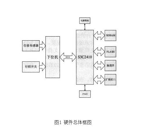
The ARM chip of the elevator buffer reset time tester Samsung S3C2410 uses TFT color LCD graphic display and touch screen operation. Various communication interfaces are reserved. The system mainly consists of four main components: control part, data acquisition part, data storage part, and input and output part. The specific hardware block diagram is shown in Figure 1 below:

The lower computer part of the system is mainly responsible for the front-end sensor data collection and storage and related communication with the upper computer. The analysis of relevant data, algorithm processing and user program design are mainly completed by the S3C2410 of the upper computer.
2.2 Data collection plan
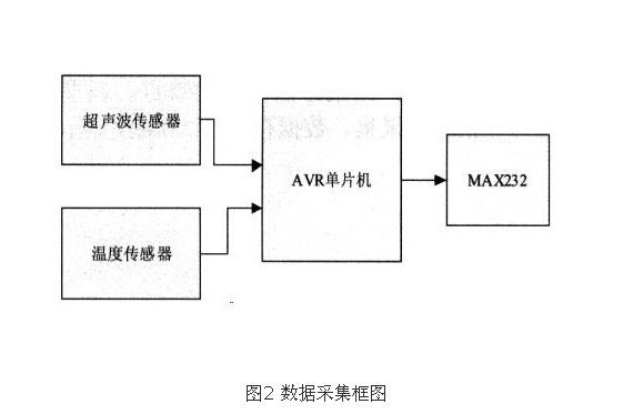
The lower computer is a computer that directly controls the equipment to obtain the equipment status, usually a PLC/single chip microcomputer or the like. The command issued by the upper computer is first given to the lower computer, and then the lower computer interprets the command into the corresponding timing signal to directly control the corresponding equipment. The lower computer reads equipment status data (general analog quantities) from time to time and converts it into a digital signal to feed back to the upper computer. In short, the real situation is very different. Both the upper and lower computers need programming and have special development systems. Figure 2 shows the hardware block diagram of data acquisition:

3 System software part:
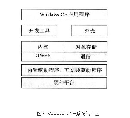
Windows CE is mainly divided into four modules, as shown in the figure. These four modules provide important operating system functions: kernel, object storage module, network and communication module and GWES module.
Windows CE also contains other optional modules to support tasks such as managing installable device drivers and supporting COM. Figure 3 shows the system structure diagram:

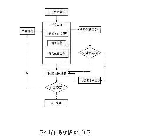
In order to port Windows CE to a specific target platform, Microsoft provides a complete set of development tools Platform Builder. This tool is provided to the operating system in an object library format so that developers can use it as a component of a specific operating system platform.
First, select the basic configuration of the production system, and select the corresponding microprocessor and board support package BSP (Board Support Packet) for the specific platform. BSP board support package (board support package) is a layer between the motherboard hardware and the driver layer program in the operating system. It is generally considered to be part of the operating system. It mainly implements support for the operating system and provides upper-layer drivers. The program provides function packages for accessing hardware device registers, allowing it to run better on the hardware motherboard. Among the components of embedded system software, there is BSP. BSP is relative to the operating system. Different operating systems correspond to different definitions of BSP. For example, the BSP of VxWorks and the BSP of Linux are relative to a certain CPU. Although the implemented functions are the same, the writing method and interface definition are completely different, so the BSP must be written according to the definition form of the system BSP (most of the BSP programming process is modified on a certain formed BSP template). Only in this way can we maintain the correct interface with the upper-layer OS and provide good support for the upper-layer OS. This tester uses the S3C2410 processor, so we modified the S3C2410-based BSP provided by Microsoft and customized the BSP to meet our requirements.
Secondly, the platform is formulated. At this stage, device drivers can be developed, and components can be appropriately cut and added. Then, the required functional modules are encapsulated and compiled to generate an OS image file. Next, transfer the image file to the target device for debugging.
Export the SDK (Soltware Development Kit) of the customized operating system and install it into the EVC to develop applications based on our customized tester hardware platform. Figure 4 shows the operating system migration flow chart:

3.2 Application software development
The main task of the operating system is to manage all hardware resources and provide a suitable operating environment for application software. After porting the Windows CE operating system to the ARM platform, the next step is to develop application software. The host computer software of this system is mainly developed in the EVC environment, using C language as the main programming language.
3.2.1 Serial communication protocol description
The module serial port baud rate is 9600, no parity, and one stop bit. Control commands are communicated through a consistent frame structure, with a frame length of 4 bytes: command + data 0 + data 1 + checksum. Check sum = the lower 8 bits of the sum of command + data 0 + data 1. The system directly operates the lower computer module through the serial port of the upper computer. The host computer sends to the host computer a command to start 16-bit distance reading: Ox22+degree+NC+SUM. When the measurement is completed, the data returned at this time is: Ox22+distance high+distance low+SUM; when the measurement is invalid, the distance high bit returned and low-bit data are Oxff. (Note: NC stands for arbitrary data, and SUM stands for validation sum.) The serial port is a stream interface device under Windows CE. It is the specific call and communication related to the conventional I/O driver of the serial device interface. combination of functions. Serial devices are treated as regular installable stream devices used to open, close, and read and write serial ports. The serial port functions of Windows CE are basically the same as those of Windows, but there are a few points worth noting: Windows CE only supports the Unicode character set, so special attention must be paid when programming; Windows CE does not support overlapping I/O operations. In all stream device drivers, CreateFile is used to open the serial port device. If the port does not exist, CreateFile returns ERROR_FILE_NOT_FOUND.

Closing a serial port is relatively simple. Calling the CloseHandle function can close an open serial port. CloseHandle has only one parameter, which is the handle returned when the CreateFile function is called to open the port. The method is as follows:
CloseHandle(hPort);
Just as you use CreateFile to open a serial port, you can use the ReadFile and WriteFile functions to read and write to a serial port. Assuming you have successfully opened the serial port by calling CreateFile, you can simply call ReadFile to read data from the serial port:

If a large amount of serial data is read or written from the main thread, the main thread will be blocked waiting for a relatively slow serial read or write operation and cannot process other messages immediately, so a separate thread is used to read and write here. serial port. For serial ports, a timeout value must also be configured, otherwise the program may fall into an infinite loop waiting for characters from the serial port. Generally, configuring the timeout value is similar to configuring the serial port. First, use the GetCommTimeouts function to obtain the timeout value of the current serial port, then modify the value of the CommTimeouts member variable, and use SetCommTimeouts to set a new timeout value.
Previous article:Migrate the mtdparts partition of u-boot-1.1.6
Next article:LCD Experiment Study Notes (7): NAND FLASH
- Popular Resources
- Popular amplifiers
- Naxin Micro and Xinxian jointly launched the NS800RT series of real-time control MCUs
- How to learn embedded systems based on ARM platform
- Summary of jffs2_scan_eraseblock issues
- Application of SPCOMM Control in Serial Communication of Delphi7.0
- Using TComm component to realize serial communication in Delphi environment
- Bar chart code for embedded development practices
- Embedded Development Learning (10)
- Embedded Development Learning (8)
- Embedded Development Learning (6)
 Professor at Beihang University, dedicated to promoting microcontrollers and embedded systems for over 20 years.
- Intel promotes AI with multi-dimensional efforts in technology, application, and ecology
- ChinaJoy Qualcomm Snapdragon Theme Pavilion takes you to experience the new changes in digital entertainment in the 5G era
- Infineon's latest generation IGBT technology platform enables precise control of speed and position
- Two test methods for LED lighting life
- Don't Let Lightning Induced Surges Scare You
- Application of brushless motor controller ML4425/4426
- Easy identification of LED power supply quality
- World's first integrated photovoltaic solar system completed in Israel
- Sliding window mean filter for avr microcontroller AD conversion
- What does call mean in the detailed explanation of ABB robot programming instructions?
- STMicroelectronics discloses its 2027-2028 financial model and path to achieve its 2030 goals
- 2024 China Automotive Charging and Battery Swapping Ecosystem Conference held in Taiyuan
- State-owned enterprises team up to invest in solid-state battery giant
- The evolution of electronic and electrical architecture is accelerating
- The first! National Automotive Chip Quality Inspection Center established
- BYD releases self-developed automotive chip using 4nm process, with a running score of up to 1.15 million
- GEODNET launches GEO-PULSE, a car GPS navigation device
- Should Chinese car companies develop their own high-computing chips?
- Infineon and Siemens combine embedded automotive software platform with microcontrollers to provide the necessary functions for next-generation SDVs
- Continental launches invisible biometric sensor display to monitor passengers' vital signs
- Application and development of filters in anti-EMI
- PCB Design
- Why can't I see the bluetooth function when running micropython on EPS32?
- Does anyone know how this kind of colored PCB is made? ?
- How to solve the problems of waterproofing, liquid level fluctuation, and water droplets sticking to the wall of the liquid level sensor?
- EEWORLD University Hall----Live Replay: Comprehensive explanation of TI MSP Academy tutorial
- TI CC2640R2F documentation for beginners
- [MM32 eMiniBoard Review] In-depth understanding of HID-2
- New Electronic Circuits Encyclopedia Volume 2 General Analog Circuits
- Parameter Analysis of Frequency Measurement Signal Using Single Chip Microcomputer


 AD745AR


 京公网安备 11010802033920号