1. LED
1.1.What is LED?
LED (light-emitting diode), commonly known as LED small lamp, is a light-emitting display device made of semiconductor materials such as gallium phosphide (GaP) that can directly convert electrical energy into light energy. When a certain current passes through the LED, it will emit light. Different LEDs can emit different colors of light, the most common ones are red, yellow, etc., as shown in the figure:
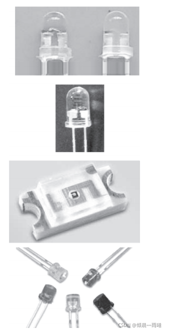
The following points are mainly explained about the appearance characteristics of LED.
(1) The color of the shell of a monochrome LED indicates its luminous color. The shell of the LED is transparent.
(2) A single-color LED has only two pins, which have positive and negative poles. A multi-color LED has three pins.
(3) The LED has a distinctive appearance, so it is easy to identify the LED.
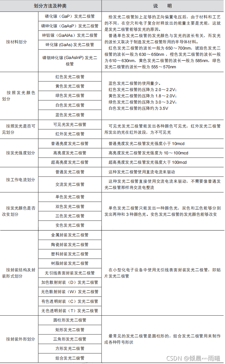
1.2. Types of LEDs
1.3. Main parameters of LED
Electrical parameters:
(1) Forward operating current IF. It refers to the forward current value when the light-emitting diode emits light normally. The operating current of the light-emitting diode is generally 10 to 20 mA.
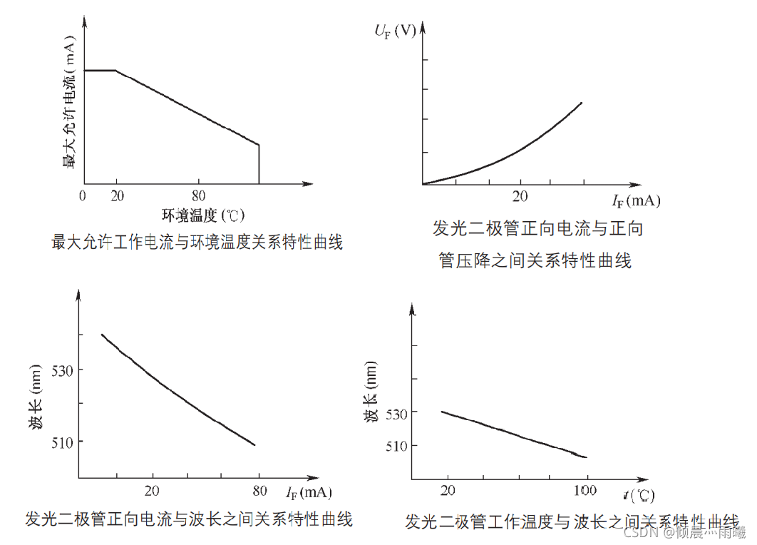
(2) Forward operating voltage UF. It is the forward operating voltage across the LED at a given forward current. It is usually measured at IF = 20mA, and the forward operating voltage of the LED is 1.4 to 3V. When the external temperature rises, the forward operating voltage of the LED will decrease.
(3) Volt-ampere characteristic. It refers to the relationship between the voltage and current of a light-emitting diode.
Limit parameters:
(1) Allowable power consumption Pm. It is the maximum value of the product of the forward DC voltage across the LED and the current flowing through it. If this value is exceeded, the LED will heat up and be damaged.
(2) Maximum forward DC current IFm. It is the maximum forward DC current allowed. If it exceeds this value, the diode will be damaged.
(3) Maximum reverse voltage URm. It is the maximum reverse voltage allowed. If the reverse voltage exceeds this value, the light-emitting diode may be damaged by breakdown.
(4) Working environment topm. It is the ambient temperature range in which the light-emitting diode can work normally. If the temperature is lower or higher than this range, the light-emitting diode will not work normally and the efficiency will be greatly reduced.
1.4. Main characteristics of LED
Volt-ampere characteristics
The volt-ampere characteristics of LEDs are similar to those of ordinary diodes, except that the forward conduction voltage of LEDs is larger. The reverse breakdown voltage of low-current LEDs is very small, ranging from 6V to more than ten volts, which is smaller than that of ordinary diodes. The figure below shows the forward volt-ampere characteristic curve of LEDs.

The figure below is the LED volt-ampere characteristic curve, which includes forward and reverse characteristics. LED has an input volt-ampere characteristic curve similar to that of a general semiconductor transistor.

The various sections of the volt-ampere characteristic curve are explained below.
(1) OA segment. This is the forward dead zone. UA is the voltage that turns on the LED.
(2) AB segment. This is the working area. In this segment, generally, as the voltage increases, the current also increases, and the luminous brightness also increases.
In this section, special attention should be paid. If no protection is added, when the forward voltage increases to a certain value, the forward voltage of the LED will decrease, while the forward current will increase. If there is no protection circuit, the LED will be burned out due to the increase in current.
(3) OC segment. This is the reverse dead zone. When a reverse voltage is applied to the light-emitting diode, it does not emit light (does not work), but there is a reverse current. This reverse current is usually very small, generally within a few microamperes. In 1990-1995, the reverse current was set at 10μA; in 1996-2000, the reverse current was set at 5μA. Currently, the reverse current is generally below 3μA, but basically 0μA.
(4) CD segment. This is the reverse breakdown region. The reverse voltage of the LED should generally not exceed 10V, and the maximum should not exceed 15V. If this voltage is exceeded, reverse breakdown will occur, causing the light-emitting diode to be scrapped.
In this section, the LED has a large reverse breakdown current (several mA). This breakdown is not a thermal breakdown and will not cause damage. Some AC sockets and AC indicator lights on AC power switches use LEDs, and the LEDs work in this section during the negative half cycle of the AC power.
Forward resistance and reverse resistance characteristics
The forward and reverse resistances of LEDs are much larger than those of ordinary diodes. Understanding this is of great guiding significance for detecting diodes.
Relationship between working current and relative luminous intensity
The figure below shows the characteristic curve of the relationship between the working current and the relative intensity of light emitted by a light-emitting diode. For a red LED, the relative intensity of light emitted increases as the forward working current increases. When the working current reaches a certain level, the curve tends to be flat (saturated), indicating that the relative intensity of light emitted tends to be saturated; for a green LED, the relative intensity of light emitted increases as the working current increases, but there is no saturation phenomenon.

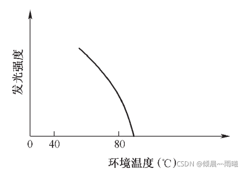
Relationship between luminous intensity and ambient temperature
The figure below shows the characteristic curve of the relationship between the luminous intensity of the LED and the ambient temperature. The lower the temperature, the greater the luminous intensity. When the ambient temperature rises, the luminous intensity will drop significantly.
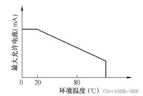
5. Relationship between maximum allowable operating current and ambient temperature
The figure below shows the characteristic curve of the maximum allowable operating current and ambient temperature. When the ambient temperature reaches a certain level, the maximum allowable operating current decreases rapidly and eventually reaches zero, which means that LEDs are more likely to be damaged in high ambient temperatures. This is also the reason why LEDs are afraid of heat.
6. Other characteristic curves
1.5.LED pin polarity identification method
In order not to affect the normal lighting of the LED, the model and polarity are not marked on the shell. Therefore, the identification of the positive and negative pins of the LED mainly depends on the appearance characteristics and the detection of the multimeter.
Pin length identification method
The picture below shows an LED that uses the length of the pins to distinguish the positive and negative polarity pins. Its two pins are one long and one short. The long one is the positive pole and the short one is the negative pole.

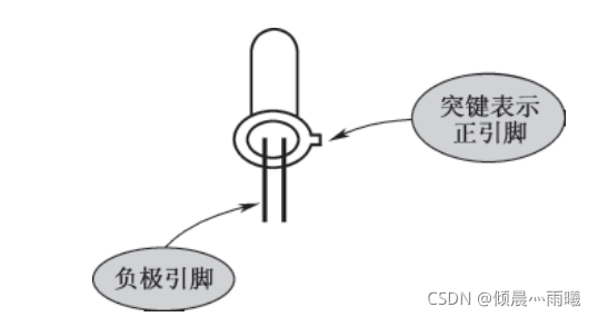
Key-type identification method
The figure below shows the method of using a key to indicate the positive polarity pin. There is a key on the LED base, and the pin closest to this key is the positive pole.
3-pin LED pin identification method
The following figure shows the pin distribution pattern and internal circuit diagram of a 3-pin LED. There are two light-emitting diodes of different colors. K is the common pin.
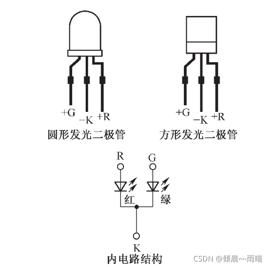
The figure below is a schematic diagram of another method for identifying the pins of a 3-pin color-changing LED. It has a protruding key, and each pin can be easily identified based on its appearance feature.

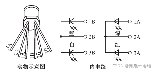
6-pin LED pin identification method
The following figure shows the pin distribution pattern and internal circuit diagram of a 6-pin LED. It has two groups of 3-pin LEDs.
1.6. Voltage-controlled and flashing LEDs
Voltage controlled LED
LED itself is a current-controlled device, that is, it will emit light when current flows through it. When in use, it needs to be connected in series with a current-limiting resistor of appropriate resistance. For the convenience of use, the LED and the current-limiting resistor are made into one piece, which can be directly connected to the two ends of the power supply when in use, thus forming a voltage-controlled LED. The figure below shows the actual picture and internal circuit of the voltage-controlled LED. The luminous colors of the voltage-controlled LED include red, yellow, green, etc. The working voltage has 6 specifications of 5V, 9V, 12V, 18V, 19V, and 24V. The commonly used one is the BTV series.

Flashing LED
The flashing LED is a special light-emitting device composed of a CMOS integrated circuit and an LED. The following figure shows the actual image and internal circuit of the flashing LED, which can be used for alarm indication and undervoltage and overvoltage indication.
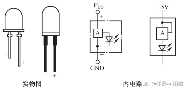
The following figure is a block diagram of the internal circuit of a flashing LED. When using a flashing LED, no other external components are required. As long as an appropriate DC working voltage (5V) is applied to both ends of its pins, it can flash and emit light. The commonly used flashing LED is the BTS series.

2. Single chip microcomputer controls LED
After writing so many introductions to LED, we should have a clear understanding of LED. Now we start to write programs for the microcontroller to control the LED.
2.1. Light up an LED
2.1.1 Program Writing
First, we build a circuit schematic in Proteus 8 Professional as shown in the figure

R1 in the figure is a current limiting resistor to prevent the LED from being damaged due to excessive current.
Then start writing the program. If you have learned C language, you should be able to program easily. If you have not learned it, it doesn’t matter, just copy it first.
#include
sbit LED = P2^3 ; // declaration of bit address, note: sbit must be lowercase, P must be uppercase
void main() // Any C program must have one and only one main function
{ // {} appear in pairs, indicating the start and end of the program
LED = 0 ; // The semicolon indicates the end of a statement, "1" indicates a high level, and "0" indicates a low level
Previous article:Introduction to 51 single chip microcomputer - digital tube
Next article:Introduction to 51 MCU - Use of Proteus 8 Professional
Recommended ReadingLatest update time:2024-11-23 11:26


![[51 Single Chip Microcomputer] My roommate learned how to use digital tubes using a King of Time computer.](https://6.eewimg.cn/news/statics/images/loading.gif)


- Popular Resources
- Popular amplifiers
-
 MCU C language programming and Proteus simulation technology (Xu Aijun)
 -
 100 Examples of Microcontroller C Language Applications (with CD-ROM, 3rd Edition) (Wang Huiliang, Wang Dongfeng, Dong Guanqiang)
 -
 Fundamentals and Applications of Single Chip Microcomputers (Edited by Zhang Liguang and Chen Zhongxiao)
 -
 Single chip microcomputer control technology (Li Shuping, Wang Yan, Zhu Yu, Zhang Xiaoyun)
- Naxin Micro and Xinxian jointly launched the NS800RT series of real-time control MCUs
- How to learn embedded systems based on ARM platform
- Summary of jffs2_scan_eraseblock issues
- Application of SPCOMM Control in Serial Communication of Delphi7.0
- Using TComm component to realize serial communication in Delphi environment
- Bar chart code for embedded development practices
- Embedded Development Learning (10)
- Embedded Development Learning (8)
- Embedded Development Learning (6)
 Professor at Beihang University, dedicated to promoting microcontrollers and embedded systems for over 20 years.
- Intel promotes AI with multi-dimensional efforts in technology, application, and ecology
- ChinaJoy Qualcomm Snapdragon Theme Pavilion takes you to experience the new changes in digital entertainment in the 5G era
- Infineon's latest generation IGBT technology platform enables precise control of speed and position
- Two test methods for LED lighting life
- Don't Let Lightning Induced Surges Scare You
- Application of brushless motor controller ML4425/4426
- Easy identification of LED power supply quality
- World's first integrated photovoltaic solar system completed in Israel
- Sliding window mean filter for avr microcontroller AD conversion
- What does call mean in the detailed explanation of ABB robot programming instructions?
- STMicroelectronics discloses its 2027-2028 financial model and path to achieve its 2030 goals
- 2024 China Automotive Charging and Battery Swapping Ecosystem Conference held in Taiyuan
- State-owned enterprises team up to invest in solid-state battery giant
- The evolution of electronic and electrical architecture is accelerating
- The first! National Automotive Chip Quality Inspection Center established
- BYD releases self-developed automotive chip using 4nm process, with a running score of up to 1.15 million
- GEODNET launches GEO-PULSE, a car GPS navigation device
- Should Chinese car companies develop their own high-computing chips?
- Infineon and Siemens combine embedded automotive software platform with microcontrollers to provide the necessary functions for next-generation SDVs
- Continental launches invisible biometric sensor display to monitor passengers' vital signs
- System Solution for Car-mounted Mobile TV Reception
- [Shanghai Hangxin ACM32F070 development board + touch function evaluation board] 01. Basic engineering & KEY & LED & BUZZER & SHELL
- Complain about the search engine you currently use...
- KiCad 5.1.7 was officially released on September 30th
- C2000 Real-time Control MCU Application in Electric Vehicles
- MPLAB Pseudo-Instructions and Macros
- System testing method for remote communication nodes
- Qorvo's Zhou Ting: Towards an ideal ultra-broadband provider
- TMS320C6000 C/C++ Runtime Environment
- Judgment method and error calculation for mismatch between compensation wire and thermocouple graduation number


 MCU C language programming and Proteus simulation technology (Xu Aijun)


 京公网安备 11010802033920号