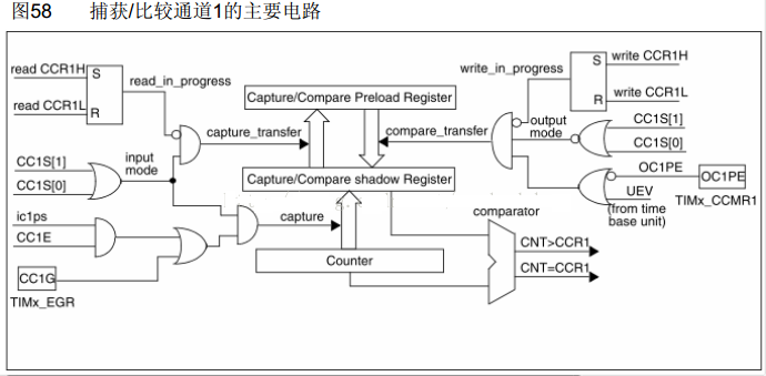
Recently, I need to use a frequency detection function when using STM8 . Fortunately, the timer of STM8S207 has an input capture function. I used to think of using the timer counting method to implement it, but since they provide this function, let’s give it a try. Since the hardware is connected to the PC1 pin, I only looked at Timer1. Other timers should be similar. After reading the information, I found that the input capture of STM8 is actually very similar to the PCA capture mode in STC12C5A60S2, but the information is not as clear and easy to understand as the latter. . .

In the capture mode, basically only the reading process is used. There is a shadow register in STM8 , but it is invisible to us. We only need to operate the preload register. And it should be noted that whether it is the counter or the capture/compare register, the high 8 bits are read/written first, and then the low 8 bits are read/written.
The document gives a process for input capture mode

[cpp] view plain copyTIM1_CCER1 &= (unsigned char)~0x02; //Rising edge or high level trigger
Finally, enable the capture function and set the CC1E bit of the TIM1_CCER1 register to 1. Since we use the interrupt mode, we also set the CC1IE bit of the TIM1_IER register to 1 to allow interrupt requests.
The complete initialization code is as follows
[cpp] view plain copyvoid signal_capture_Init(void)
{
TIM1_CNTRH = 0x00; // Clear the high 8 bits of the counter
TIM1_CNTRL = 0x00; // Clear the lower 8 bits of the counter
TIM1_PSCRH = 0x00; //Counter clock division high 8 bits
TIM1_PSCRL = 0x10; //Counter clock frequency division low 8 bits 16 frequency division
TIM1_CCER1 &= (unsigned char)~0x01; //Clear CC1E bit in TIM1_CCER1 before configuring TI M1_CCMR1
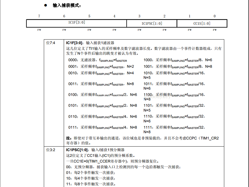
TIM1_CCMR1 = 0x01; //Configure CC1S bit in TIM1_CCMR1 to 1, CC1 channel is configured as input, IC1 is mapped to TI1FP1
//No filter, no prescaler (each edge detected on the capture input port triggers a capture)
TIM1_CCER1 &= (unsigned char)~0x02; //Rising edge or high level trigger
TIM1_IER |= 0x02; //CC1IE=1, enable capture/compare 1 interrupt
TIM1_CCER1 |= 0x01; //Capture enable
TIM1_CR1 |= 0x01; // Enable timer/counter
}
When an input capture occurs, the counter value is transferred to the TIM1_CCR1 register. The clock source of the timer is set to 16 division in the program.

After the frequency division, the frequency of the counter is 1MHz. The frequency division is used here mainly to avoid the counter overflow, which also reduces the accuracy. At the same time, the initial value of the counter is set to 0. The default counting mode of the counter is to count up. After reaching the maximum value, it starts counting from 0 again.
The interrupt handling code is as follows
[cpp] view plain copy@far @interrupt void signal_capture_irq (void)
{
if(TIM1_SR1&0x02)
{
TIM1_SR1 &= (unsigned char)~0x02; //Clear CC1IF flag
if(vsync_cap_data_old == 0x00)
{//The first capture interrupt comes
vsync_cap_data_old = TIM1_CCR1H; //Read the high 8 bits first
vsync_cap_data_old = (unsigned int)(vsync_cap_data_old<<8) + TIM1_CCR1L; // read the lower 8 bits of data again
}
else
{
//The second capture interrupt comes
vsync_cap_data_new = TIM1_CCR1H; //Read the high 8 bits first
vsync_cap_data_new = (unsigned int)(vsync_cap_data_new<<8) + TIM1_CCR1L; // read
TIM1_IER &= (unsigned char)~0x02; //Disable channel 1 capture/compare interrupt
TIM1_CR1 &= (unsigned char)~0x01; //Stop the counter
if(vsync_cap_data_new > vsync_cap_data_old)
vsync_period = (vsync_cap_data_new - vsync_cap_data_old);
else
vsync_period = 0xFFFF + vsync_cap_data_new - vsync_cap_data_old;
vsync_cap_data_old = 0x00;
isCaptureOver = 1;
}
}
}
We capture two interrupts and calculate the time difference.
[cpp] view plain copyif(isCaptureOver)
{
//If the capture is complete, process the data
cmd_puts("period:");
cmd_hex((unsigned char)(vsync_period>>8));
cmd_hex((unsigned char)vsync_period);
TIM1_CNTRH = 0x00; // Clear the high 8 bits of the counter
TIM1_CNTRL = 0x00; // Clear the lower 8 bits of the counter
TIM1_IER |= 0x02; //CC1IE=1, enable capture/compare 1 interrupt
TIM1_CR1 |= 0x01; // Enable timer/counter
isCaptureOver = 0;
}
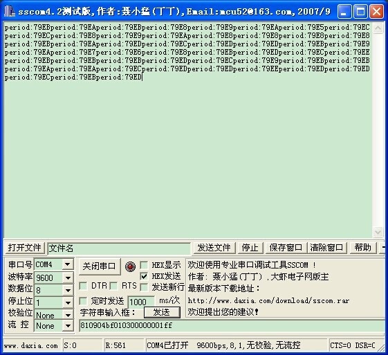
Here only the cycle is output from the serial port, the results are as follows

It can be seen that the period fluctuates within a range. We take a value 0x79ED to calculate. The corresponding frequency f=1000000/0x79ED=32.0379Hz is still relatively close to our actual input frequency of 30Hz. The error is a bit large, and it can be further improved through the code
Previous article:Summary of several memory leaks in MCU C language
Next article:Detailed explanation of MCU SPI bus timing
- Popular Resources
- Popular amplifiers
 Professor at Beihang University, dedicated to promoting microcontrollers and embedded systems for over 20 years.
- LED chemical incompatibility test to see which chemicals LEDs can be used with
- Application of ARM9 hardware coprocessor on WinCE embedded motherboard
- What are the key points for selecting rotor flowmeter?
- LM317 high power charger circuit
- A brief analysis of Embest's application and development of embedded medical devices
- Single-phase RC protection circuit
- stm32 PVD programmable voltage monitor
- Introduction and measurement of edge trigger and level trigger of 51 single chip microcomputer
- Improved design of Linux system software shell protection technology
- What to do if the ABB robot protection device stops
- Allegro MicroSystems Introduces Advanced Magnetic and Inductive Position Sensing Solutions at Electronica 2024
- Car key in the left hand, liveness detection radar in the right hand, UWB is imperative for cars!
- After a decade of rapid development, domestic CIS has entered the market
- Aegis Dagger Battery + Thor EM-i Super Hybrid, Geely New Energy has thrown out two "king bombs"
- A brief discussion on functional safety - fault, error, and failure
- In the smart car 2.0 cycle, these core industry chains are facing major opportunities!
- The United States and Japan are developing new batteries. CATL faces challenges? How should China's new energy battery industry respond?
- Murata launches high-precision 6-axis inertial sensor for automobiles
- Ford patents pre-charge alarm to help save costs and respond to emergencies
- New real-time microcontroller system from Texas Instruments enables smarter processing in automotive and industrial applications
- EEWORLD University - How to use independent measurement ADC to design high-precision CT phase meter
- A collection of selected PCB design resources, free points download for a limited time
- MCU model confirmation and decryption
- [Zero-knowledge ESP8266 tutorial] Quick start 25 Blynk control RGB LED
- Need a 10uh inductor, ESR < 0.2Ω, saturation current > 0.8A
- Ti DSP optimization basic strategy
- Bluetooth Protocol Stack-01
- Scattered Noise Figure
- [Mil MYC-JX8MPQ Review] Running TDengine
- Digital Integrated Circuit Design: From VLSI Architecture to CMOS Manufacturing.pdf

 SP0-2505-6


 京公网安备 11010802033920号