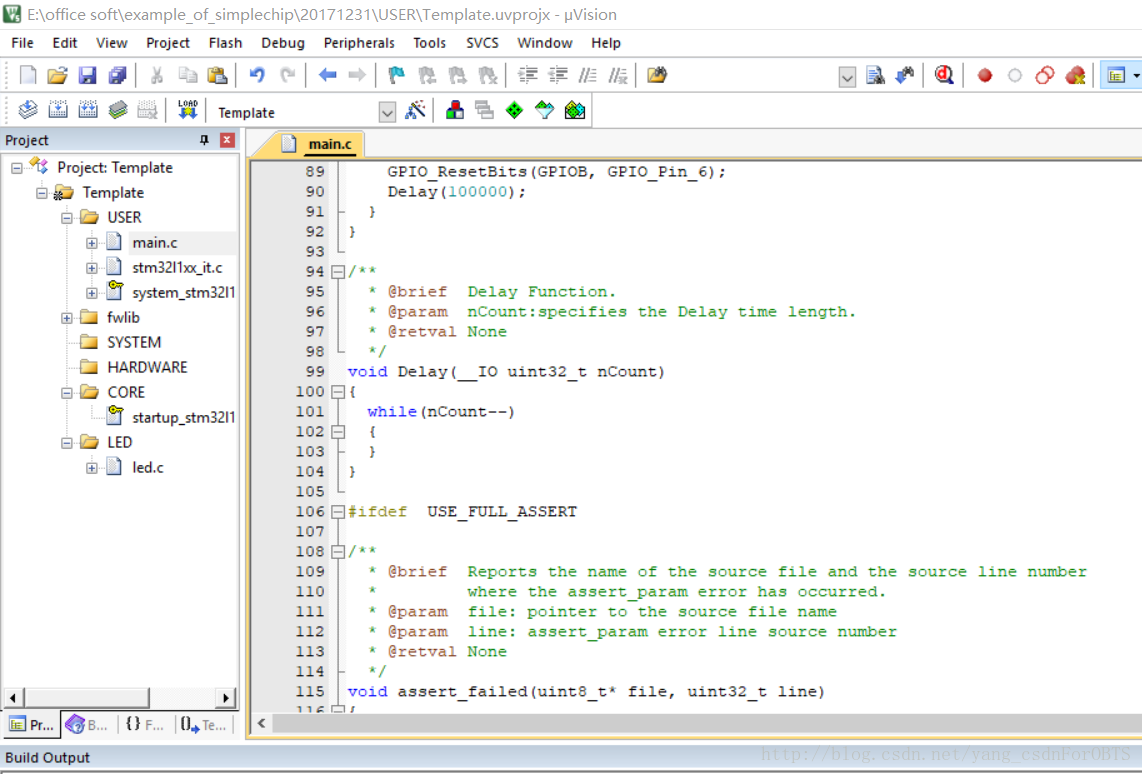
Open the previously created project, as shown in the figure below (the creation of the Keil project is in the previous article, and students who don’t know can turn to the previous article.)
(The picture above is a completed project)
Then, open the LED light routine in the routine package of the corresponding development board version we downloaded earlier.
(The path is: en.stsw-stm32077 \STM32L1xx_StdPeriph_Lib_V1.3.1 \project\STM32L1xx_StdPeriph_Examples \GPIO \IOToggle)
Find the mian.c file and open it, select and copy all the contents
Go back to the project we have created before, open the main.c file, clear it, and paste the contents of main.c in the GPIO file into main.c of our project.
At this point, you can see that there are many errors. Next, you need to modify the program (because the definitions of many parameters in the routine are not accurately corresponding to each board, so they need to be modified. In order to achieve the simplest LED light lighting function, we will delete the redundant programs)
The first step is to delete two programs:
(The picture above shows the first program that was deleted)
(The picture above shows the second program that needs to be deleted - all the contents in the while loop)
OK, now the main function has been basically deleted.
The second step is to look at the board. I use STM32L152c-discovery, and the ports of my two LED lights are PB7 and PB6 respectively (the following content needs to be changed according to the board situation)
So, I have to change the D port in the example to the B port first.
(Both of the above should be changed to B, because my LED light is connected to port B)
Step 3: Configure the output mode
Change GPIO_PIN_X and GPIO_PIN_Y to GPIO_Pin_6 and GPIO_Pin_7 respectively. Note that there are two places to change. One is to change XY to 67, because my pins are PB6 and PB7, and the other is to change PIN to Pin, because the mode defined in my version of the library function is like this. After the modification:
Step 4: Modify the loop content (key steps to control LED lights)
Add the program shown in the figure above into while (where you just deleted the second program).
Step 5. Add the declaration of the Delay function (I don’t know if I accidentally deleted the declaration before, or if it was not originally included in the example. If yours has it, you don’t need to add it)
At this point, the program modification is complete, rebuild, and then burn, you can see the two LED lights flashing in a cycle.
It is particularly emphasized that the modification of the program here depends on the port and connection status of your board itself, and you need to check the corresponding ones! (In addition, the explanation of the program is in the picture above, and only two very simple programs are needed!)
Previous article:Use STM32GPIO port to light up the LED (library function)
Next article:STM32-Serial port IAP upgrade
- Popular Resources
- Popular amplifiers
 Professor at Beihang University, dedicated to promoting microcontrollers and embedded systems for over 20 years.
- LED chemical incompatibility test to see which chemicals LEDs can be used with
- Application of ARM9 hardware coprocessor on WinCE embedded motherboard
- What are the key points for selecting rotor flowmeter?
- LM317 high power charger circuit
- A brief analysis of Embest's application and development of embedded medical devices
- Single-phase RC protection circuit
- stm32 PVD programmable voltage monitor
- Introduction and measurement of edge trigger and level trigger of 51 single chip microcomputer
- Improved design of Linux system software shell protection technology
- What to do if the ABB robot protection device stops
- Innovation is not limited to Meizhi, Welling will appear at the 2024 China Home Appliance Technology Conference
- Innovation is not limited to Meizhi, Welling will appear at the 2024 China Home Appliance Technology Conference
- Huawei's Strategic Department Director Gai Gang: The cumulative installed base of open source Euler operating system exceeds 10 million sets
- Download from the Internet--ARM Getting Started Notes
- Learn ARM development(22)
- Learn ARM development(21)
- Learn ARM development(20)
- Learn ARM development(19)
- Learn ARM development(14)
- Learn ARM development(15)
- FPGA-to-ASIC integration brings flexibility to microcontrollers
- Award-winning live broadcast: Registration for the introduction of ON Semiconductor's photovoltaic and energy storage products is now open~
- CircuitPython 7.0.0 Alpha 4 released
- How to Erase the Contents of EPCS in Altera FPGA Configuration Device
- [Problem Feedback] Anlu TangDynasty ChipWatcher network sorting confusion issue
- Instrument and control system grounding and shielding training materials
- ART-Pi evaluates the display driver LTDC+SDRAM of H7 RGB screen
- 64 yuan group purchase (5 left): Thumb board NUCLEO-L432KC, limited quantity, come quickly
- CCS uninstallation and installation process and problems encountered
- [Summary] EEWorld invites you to disassemble (fifth issue) - disassemble the power strip and learn to evaluate the circuit


 BA3121F-E2


 京公网安备 11010802033920号