1. Clock drive
There are three different clock sources that can be used to drive the system clock:
● Internal high-speed (HSI) 8MHz RC oscillator clock
● External high-speed (HSE) oscillator clock
● PLL clock
2. Introduction to system clock
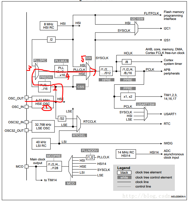
In STM32, when we say we want to configure the system clock, we mean to configure the red part "SYSCLK (system clock)" in the figure below. The system clock SYSCLK is the clock source for most of the working periods in STM32. As shown in the figure below, the system clock can be configured for IIC, AHB, APB, DMA and other clocks.
3. Example of system clock configuration
: If an 8MHZ crystal oscillator is connected externally, it needs to be configured as a 48MHZ system clock.
Analysis: Because we need to use an 8MHZ external clock to get a 48MHZ system clock, we need to multiply it by 6 times without frequency division to get the system clock. Therefore, the route I plan to configure is shown in the figure below. 
3.1 Because we need to get a 48MHZ system clock, we use the HSE external oscillator clock to drive it. In the RCC->CR register, the HSEON bit is set to 1, which means that the HSE oscillator is turned on;
3.2 It is set by hardware to indicate whether the HSE oscillator is stable. Still in the RCC-CR register, when the HSE oscillator is ready, the hardware will set the HSERDY bit to 1.
3.3 It should be clear from the figure that the next step is to perform the RCC->CFGR2 register example PREDIV frequency division operation, but please note that PREDIV[3:0] PREDIV frequency division factor
These bits are used to set or clear the PREDIV frequency division factor. These bits can only be rewritten when the PLL is turned off. So the PLL should be turned off before this. So turn off PLLON in the RCC->CR register. Wait for the PLLRDY bit to lock.
3.4 Start the PREDIV division operation of the RCC->CFGR2 register, but because we do not divide but multiply, the PREDIV[3:0] PREDIV division factor is 0000 (no division).
3.5 Start by setting the PLLSRC (input clock source) switch in RCC->CFGR to 1 to select HSE/PREDIB as the PLL input clock. And enter the PLLMUL in RCC->CFGR to select the multiplication. We want 6 times the frequency, so select the multiplication factor of 6 (0100)
3.6 After the multiplication is completed, enable the PLLON bit of the RCC->CR register, and wait for the hardware to set the PLLRDY in the RC->CR register.
3.7 Select the PLLCLK output as the system clock when passing the SW switch
3.8 Enable the GPIO clock
void SystemClock(void)
{
RCC->CR|=RCC_CR_HSEON;
while(!(RCC->CR&RCC_CR_HSERDY));
RCC->CR&=~RCC_CR_PLLON;
while(RCC->CR&RCC_CR_PLLRDY);
RCC->CFGR2=RCC_CFGR2_PREDIV_DIV1;
RCC->CFGR=RCC_CFGR_PLLSRC|RCC_CFGR_PLLMUL6;
RCC->CR|=RCC_CR_PLLON;
while(!RCC->CR&RCC_CR_PLLRDY);
RCC->CFGR=(RCC->CFGR&~RCC_CFGR_SW)|RCC_CFGR_SW_PLL;
while((RCC->CFGR&RCC_CFGR_SWS)!=RCC_CFGR_SWS_1);
RCC->AHBENR|=RCC_AHBENR_GPIOAEN;
return;
}
Previous article:Clock configuration after STM32F4 board crystal oscillator change
Next article:STM32 system clock default settings
- Popular Resources
- Popular amplifiers
 Professor at Beihang University, dedicated to promoting microcontrollers and embedded systems for over 20 years.
- LED chemical incompatibility test to see which chemicals LEDs can be used with
- Application of ARM9 hardware coprocessor on WinCE embedded motherboard
- What are the key points for selecting rotor flowmeter?
- LM317 high power charger circuit
- A brief analysis of Embest's application and development of embedded medical devices
- Single-phase RC protection circuit
- stm32 PVD programmable voltage monitor
- Introduction and measurement of edge trigger and level trigger of 51 single chip microcomputer
- Improved design of Linux system software shell protection technology
- What to do if the ABB robot protection device stops
- Allegro MicroSystems Introduces Advanced Magnetic and Inductive Position Sensing Solutions at Electronica 2024
- Car key in the left hand, liveness detection radar in the right hand, UWB is imperative for cars!
- After a decade of rapid development, domestic CIS has entered the market
- Aegis Dagger Battery + Thor EM-i Super Hybrid, Geely New Energy has thrown out two "king bombs"
- A brief discussion on functional safety - fault, error, and failure
- In the smart car 2.0 cycle, these core industry chains are facing major opportunities!
- The United States and Japan are developing new batteries. CATL faces challenges? How should China's new energy battery industry respond?
- Murata launches high-precision 6-axis inertial sensor for automobiles
- Ford patents pre-charge alarm to help save costs and respond to emergencies
- New real-time microcontroller system from Texas Instruments enables smarter processing in automotive and industrial applications
- The states of the terminal device in the TI ZigBee protocol stack involved in the protocol stack
- Shanghai Hangxin ACM32F070 Development Board + Touch Function Evaluation Board Evaluation - Chapter 6 CAN Error Handling
- Has anyone encountered Ubuntu 20.04's suspended animation?
- What is the voltage of Q802 pin 3?
- About 51 single chip microcomputer combined with protuce to realize the flashing of LED lights
- Why is there an error when adding the LWIP protocol stack using the DAVE environment for XMC4800?
- RSL10 Bluetooth SoC Mobile Application Construction
- RF circuit layout summary
- SPI settings for msp430f149
- [N32L43x Review] 9. Complementary PWM, Dead Zone Test


 LT1880IS5#PBF


 京公网安备 11010802033920号