Regardless of the microcontroller, if you want to control the LED light, you can only do so by controlling the level of the I/O pin of the microcontroller chip.
The same is true for ST microcontrollers. On ST microcontrollers, I/O pins can be set by software to various functions, such as input or output, so they are called GPIO (General-purpose I/O). The
GPIO pins are divided into different groups such as GPIOA, GPIOB...GPIOG. Each group of ports is divided into 0~15, for a total of 16 different pins.
For different types of chips, the number of port groups and pins is different. For details, please refer to the datasheet of the corresponding ST microcontroller chip model.
According to the GPIO characteristics of the ST microcontroller, the steps to control the LED light are as follows:
1. Select the specific pin to be controlled from the many GPIO port pins [the control pin connected to the LED]
2. Configure the specific function required by the GPIO according to the peripheral
3. Control the LED on and off by setting the GPIO output voltage
Circuit Diagram
From the circuit diagram, we can see that the low level LED is on and the high level LED is off
So we set up the following program:
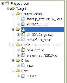
The following is library function programming, which requires loading the following library files
main.c
/*********************************************************
* Platform: MDKARM 5.14
* Main control: STM32F103RCT6
**********************************************************/
#include "stm32f10x.h"
#include "led.h"
//Delay function
void Delay(unsigned int t)
{
while(t != 0)
{
t--;
}
}
int main (void)
{
LED_Heat();
while (1) //Step 3
{
LED_Not(0); //LED flashes alternately on and off
for (j=0; j<30; j++)
{
Delay(60000);
}
}
}
led.c
#include "led.h"
//LED port initialization//step 2
void LED_Init(void)
{
GPIO_InitTypeDef GPIO_InitStructure; //Define a structure of type GPIO_InitTypeDef
RCC_APB2PeriphClockCmd( RCC_APB2Periph_GPIOC, ENABLE); // Enable the GPIO peripheral clock
GPIO_InitStructure.GPIO_Pin = GPIO_Pin_0 | GPIO_Pin_1 | GPIO_Pin_2 | GPIO_Pin_3; //Select control pin //Step 1
GPIO_InitStructure.GPIO_Mode = GPIO_Mode_Out_PP; //Set the pin to general push-pull output
GPIO_InitStructure.GPIO_Speed = GPIO_Speed_50MHz; //Set the speed of the control pin
GPIO_Init(GPIOC, &GPIO_InitStructure); //Initialize the structure
GPIO_SetBits(GPIOC, GPIO_Pin_0 | GPIO_Pin_1 | GPIO_Pin_2 | GPIO_Pin_3); //Initialize LED off
}
// Light up 1 LED
void LED_On(int n)
{
switch(n)
{
case 0: GPIO_ResetBits(GPIOC,GPIO_Pin_0); //Control pin to output low level
break;
case 1: GPIO_ResetBits(GPIOC,GPIO_Pin_1);
break;
case 2: GPIO_ResetBits(GPIOC,GPIO_Pin_2);
break;
case 3: GPIO_ResetBits(GPIOC,GPIO_Pin_3);
break;
default: break;
}
}
//
void LED_Off(int n)
{
switch(n)
{
case 0: GPIO_SetBits(GPIOC,GPIO_Pin_0); //Control pin to output high level
break;
case 1: GPIO_SetBits(GPIOC,GPIO_Pin_1);
break;
case 2: GPIO_SetBits(GPIOC,GPIO_Pin_2);
break;
case 3: GPIO_SetBits(GPIOC,GPIO_Pin_3);
break;
default: break;
}
}
void LED_Not(int n)
{
switch(n)
{
case 0: GPIO_WriteBit(GPIOC, GPIO_Pin_0,(BitAction)(1-(GPIO_ReadOutputDataBit(GPIOC, GPIO_Pin_0))));
break;
case 1: GPIO_WriteBit(GPIOC, GPIO_Pin_1,(BitAction)(1-(GPIO_ReadOutputDataBit(GPIOC, GPIO_Pin_1))));
break;
case 2: GPIO_WriteBit(GPIOC, GPIO_Pin_2,(BitAction)(1-(GPIO_ReadOutputDataBit(GPIOC, GPIO_Pin_2))));
break;
case 3: GPIO_WriteBit(GPIOC, GPIO_Pin_3,(BitAction)(1-(GPIO_ReadOutputDataBit(GPIOC, GPIO_Pin_3))));
break;
default: break;
}
}
After compiling and downloading to MCU, you can see the LED flashing
Previous article:STM32F401 ILI9235 LCD screen 2.8 inch driver experience
Next article:STM32F103RCT6 pin functions and usage
- Popular Resources
- Popular amplifiers
- Learn ARM development(16)
- Learn ARM development(17)
- Learn ARM development(18)
- Embedded system debugging simulation tool
- A small question that has been bothering me recently has finally been solved~~
- Learn ARM development (1)
- Learn ARM development (2)
- Learn ARM development (4)
- Learn ARM development (6)
 Professor at Beihang University, dedicated to promoting microcontrollers and embedded systems for over 20 years.
- LED chemical incompatibility test to see which chemicals LEDs can be used with
- Application of ARM9 hardware coprocessor on WinCE embedded motherboard
- What are the key points for selecting rotor flowmeter?
- LM317 high power charger circuit
- A brief analysis of Embest's application and development of embedded medical devices
- Single-phase RC protection circuit
- stm32 PVD programmable voltage monitor
- Introduction and measurement of edge trigger and level trigger of 51 single chip microcomputer
- Improved design of Linux system software shell protection technology
- What to do if the ABB robot protection device stops
- Analysis of the application of several common contact parts in high-voltage connectors of new energy vehicles
- Wiring harness durability test and contact voltage drop test method
- From probes to power supplies, Tektronix is leading the way in comprehensive innovation in power electronics testing
- From probes to power supplies, Tektronix is leading the way in comprehensive innovation in power electronics testing
- Sn-doped CuO nanostructure-based ethanol gas sensor for real-time drunk driving detection in vehicles
- Design considerations for automotive battery wiring harness
- Do you know all the various motors commonly used in automotive electronics?
- What are the functions of the Internet of Vehicles? What are the uses and benefits of the Internet of Vehicles?
- Power Inverter - A critical safety system for electric vehicles
- Analysis of the information security mechanism of AUTOSAR, the automotive embedded software framework
- Share some of my experiences as a part-time communication designer
- EEWORLD University Hall----Live Replay: Energy Saving and Carbon Reduction-Omron Relay, Switch, and Connector Solutions for Photovoltaic Inverter/Energy Storage Systems
- Nonlinear Compensation Method for Sensor Bridge Circuit
- DIY_boostxl-k350qvg under the recent proofing storm
- Today is 520, another beautiful day for confession. What actions will you take?
- Design and Implementation of Digital Video Conversion Interface Based on FPGA
- CR Micro's 8-bit microcontroller CS98P154 with OTP ROM
- [Lazy people take care of fish tank control system] Debug method in ON Semiconductor IDE environment
- W5500 UDP Issues
- Where should the fuse be connected?


 UPC393GR-9LG-A


 京公网安备 11010802033920号