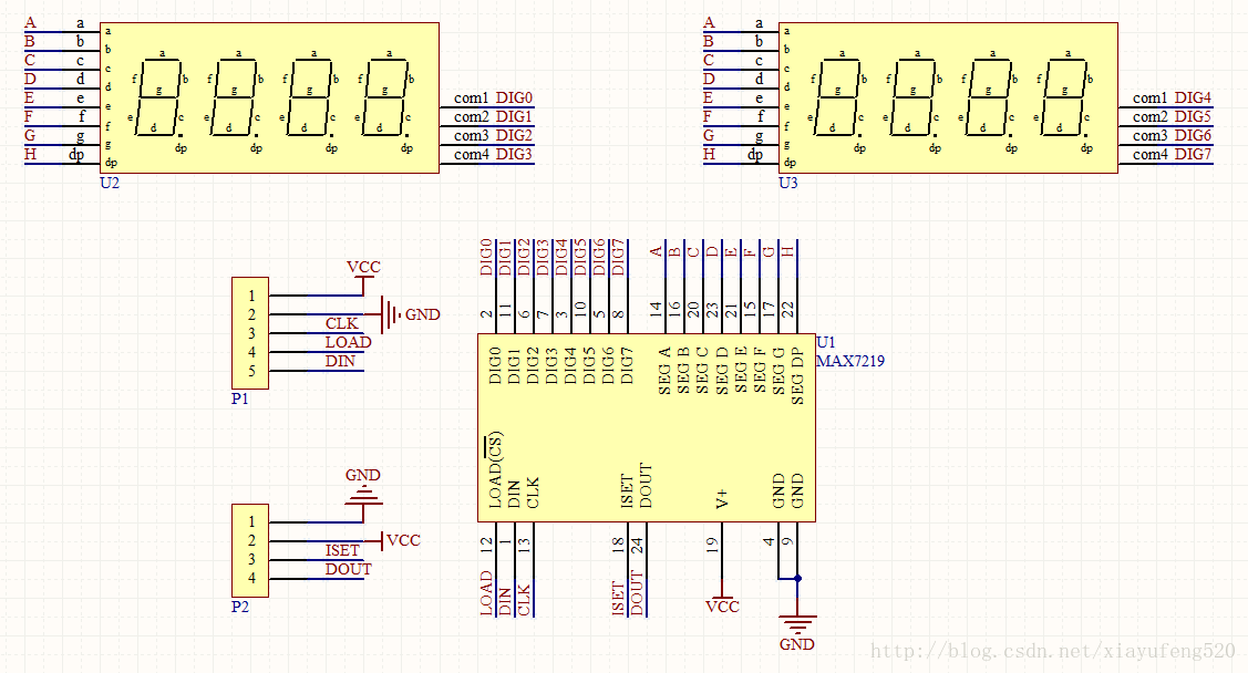
89C52 controls MAX7219 to drive digital tubes, providing source code, schematic diagram, welding diagram, etc. Links are at the end of the article.
Schematic
Source code
max7219.h
/**********************************************************
* File name: MAX7219.H
* Description: MAX7219 driver package program
**********************************************************/
#ifndef _MAX7219_H_
#define _MAX7219_H_
#include
#include
//Pin definition
sbit MAX7219_CS = P2^6;
sbit MAX7219_MOSI = P2^5;
sbit MAX7219_CLK = P2^7;
//Function register macro definition
#define DECODEMODE 0X09 //Decoding control register address
#define INTENSITY 0X0A //Brightness control register address
#define SCANLIMIT 0X0B //Scan limit register address
#define SHUTDOWN 0X0C //Shutdown mode register address
#define DISPTEST 0X0F //Test control register address
//Function definition
void MAX7219_WriteByte(unsigned char temp);
void MAX7219_Write(unsigned char addr, unsigned char dat);
void MAX719_Init(void);
#endif
MAX7219.c
/**********************************************************
* File name: MAX7219.c
* Description: MAX7219 driver package program
**********************************************************/
#include "max7219.h"
/**************************************************************
** Function name: void MAX7219_WriteByte(unsigned char date)
** Function description: Write a byte to MAX7219
** Input: unsigned char date byte content
** Global variables: None
** Calling module: None
** illustrate:
** Note:
**************************************************************/
void MAX7219_WriteByte(unsigned char date)
{
unsigned char i,temp;
for(i = 0; i < 8; i++)
{
MAX7219_CLK = 0;
temp = date & 0X80;
date = date<<1;
if(temp == 0X80)
MAX7219_MOSI = 1;
else
MAX7219_SMOKE = 0;
MAX7219_CLK = 1; //The rising edge of the clock sends the data into the register and locks it
}
}
/**************************************************************
** Function name: void MAX7219_Write(unsigned char addr, unsigned char dat)
** Function description: Write instructions to MAX7219
** Input: unsigned char addr address
unsigned char dat data
** Global variables: None
** Calling module: None
** illustrate:
** Note:
**************************************************************/
void MAX7219_Write(unsigned char addr, unsigned char dat)
{
MAX7219_CS = 0; //Register open, waiting for data to be sent
_nop_();
MAX7219_WriteByte(addr); //Select register address
_nop_();
MAX7219_WriteByte(dat); //Select the command for the chip to execute
_nop_();
MAX7219_CS = 1; //After the 16th rising edge and before the 17th rising edge, CLK must be pulled high, otherwise the data will be lost
}
/**************************************************************
** Function name: void MAX7219_Init(void)
** Function description: MAX7219 initialization
** Input: None
** Global variables: None
** Calling module: None
** illustrate:
** Note:
**************************************************************/
void MAX7219_Init(void)
{
MAX7219_Write(SHUTDOWN, 0x01); //Shutdown mode register; shutdown state, the lowest bit D0 = 0; normal state, the lowest bit D0 = 1
MAX7219_Write(DISPTEST, 0x00); //Display test register; in test state, the lowest bit D0 = 1, all bits are displayed brightly; in normal working state, the lowest bit D0 = 1
MAX7219_Write(DECODEMODE, 0xff); //decoding control register; 0XFF, full decoding
MAX7219_Write(SCANLIMIT, 0x07); //Scan limit register; set the number of LEDs to be displayed (1~8). If it is set to 0xX4, LEDs 0~5 will be displayed.
MAX7219_Write(INTENSITY, 0x08); //Brightness control register; there are 16 levels to choose from, used to set the display brightness of the LED, 0X00-0X0F
}
Previous article:Use 51 to simulate I2C slave program
Next article:51 interrupt priority and interrupt nesting
- Popular Resources
- Popular amplifiers
 Professor at Beihang University, dedicated to promoting microcontrollers and embedded systems for over 20 years.
- LED chemical incompatibility test to see which chemicals LEDs can be used with
- Application of ARM9 hardware coprocessor on WinCE embedded motherboard
- What are the key points for selecting rotor flowmeter?
- LM317 high power charger circuit
- A brief analysis of Embest's application and development of embedded medical devices
- Single-phase RC protection circuit
- stm32 PVD programmable voltage monitor
- Introduction and measurement of edge trigger and level trigger of 51 single chip microcomputer
- Improved design of Linux system software shell protection technology
- What to do if the ABB robot protection device stops
- Learn ARM development(22)
- Learn ARM development(21)
- Learn ARM development(20)
- Learn ARM development(19)
- Learn ARM development(14)
- Learn ARM development(15)
- Analysis of the application of several common contact parts in high-voltage connectors of new energy vehicles
- Wiring harness durability test and contact voltage drop test method
- From probes to power supplies, Tektronix is leading the way in comprehensive innovation in power electronics testing
- From probes to power supplies, Tektronix is leading the way in comprehensive innovation in power electronics testing
- A simple pull-up and pull-down circuit causes the control chip to heat up!
- I would like some advice on how to import .brd files into DXP
- 【BLE 5.3 wireless MCU CH582】12. MounRiver IDE usage record
- LC High Pass Filter
- [RT-Thread reading notes] Part 2: Implementing multithreading
- Design of two-choice multiplexer excitation
- VGA Display Circle - Simple Design and Application FPGA
- Internet of Things (IoT) solutions based on CC3120/CC3220 products
- MSP430 touch button
- LIS3DH X-axis data output abnormality


 MCP6541T-I/MS


 京公网安备 11010802033920号