This article is reproduced from http://blog.csdn.net/charmingsun/article/details/50802267. This tutorial aims to light up an LED lamp to demonstrate the general method of developing STM32 programs using STM32CubeMX, Keil, and ST-Link.
STM32F4xx HAL driver instructions2. Create a new STM32CubeMX project
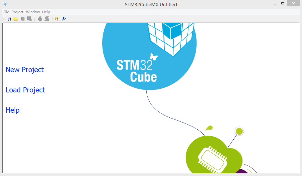
Open STM32CubeMX and click New Project:
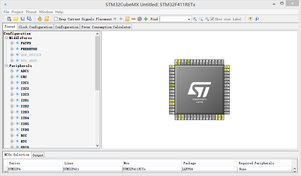
Select Series, Lines, Package, then select the model of your MCU and click OK: (My MCU is STM32F411RE, 64-pin LQFP package) 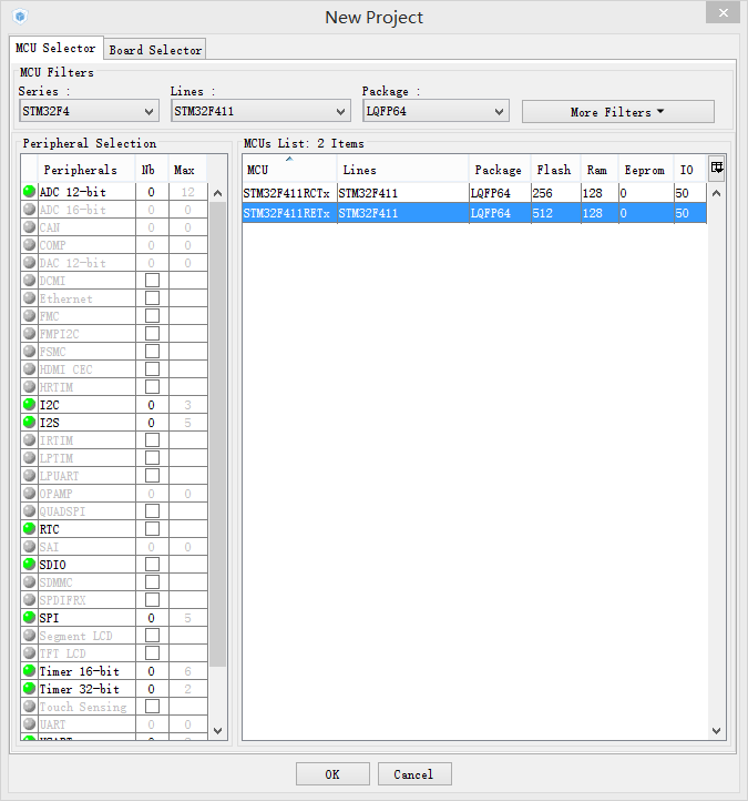
Now a STM32CubeMX project has been created:
3. Configure the corresponding pins and then generate the Keil project
Open the development board schematic and check the pins corresponding to the LED light: (As shown in the figure, let the PA5 pin output a high level to light up the LED) 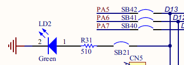
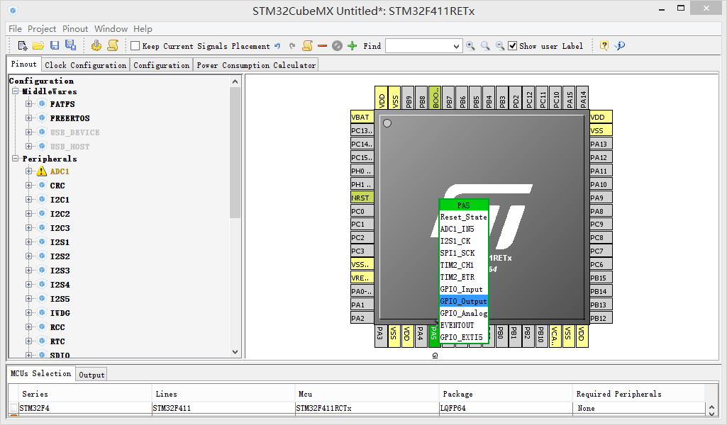
Click Pinout, then click the pin corresponding to the LED light, and select the GPIO_Output mode: (Set PA5 to the output mode of the general input and output port. For details, please refer to the GPIO introduction in the Reference manual)
Since this routine does not require the configuration of clocks, middleware and peripherals, nor does it require the calculation of power consumption, the Clock Configuration, Configuration, and Power Consumption Caculator remain default.
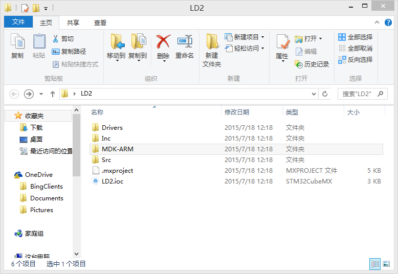
Click Project->Settings in the menu bar, enter the STM32CubeMX project name, save path, and your own tool chain/integrated compilation environment, keep the settings in Code Generator as default, and then click OK: (My STM32CubeMX project name is LD2, the save path is the desktop, and the integrated compilation environment is Keil 5) 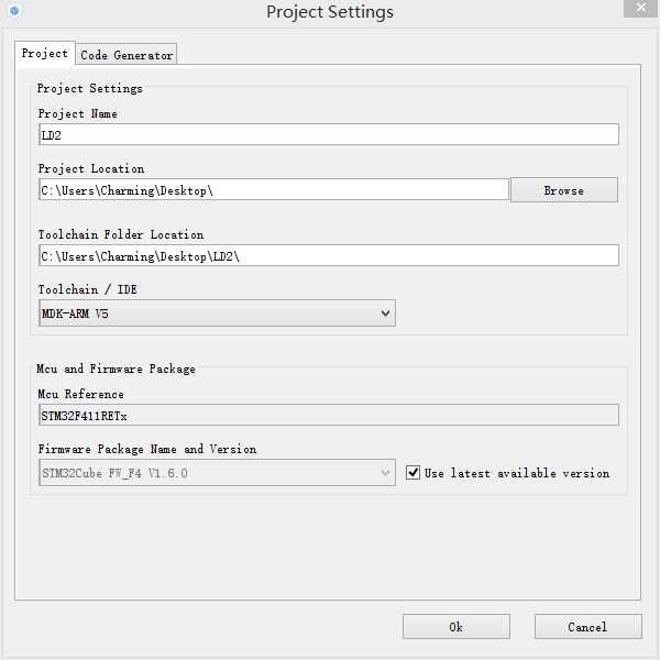
Then click Project->Generate Code in the menu bar, or click 
4. Add your own code to the Keil project, then compile and download
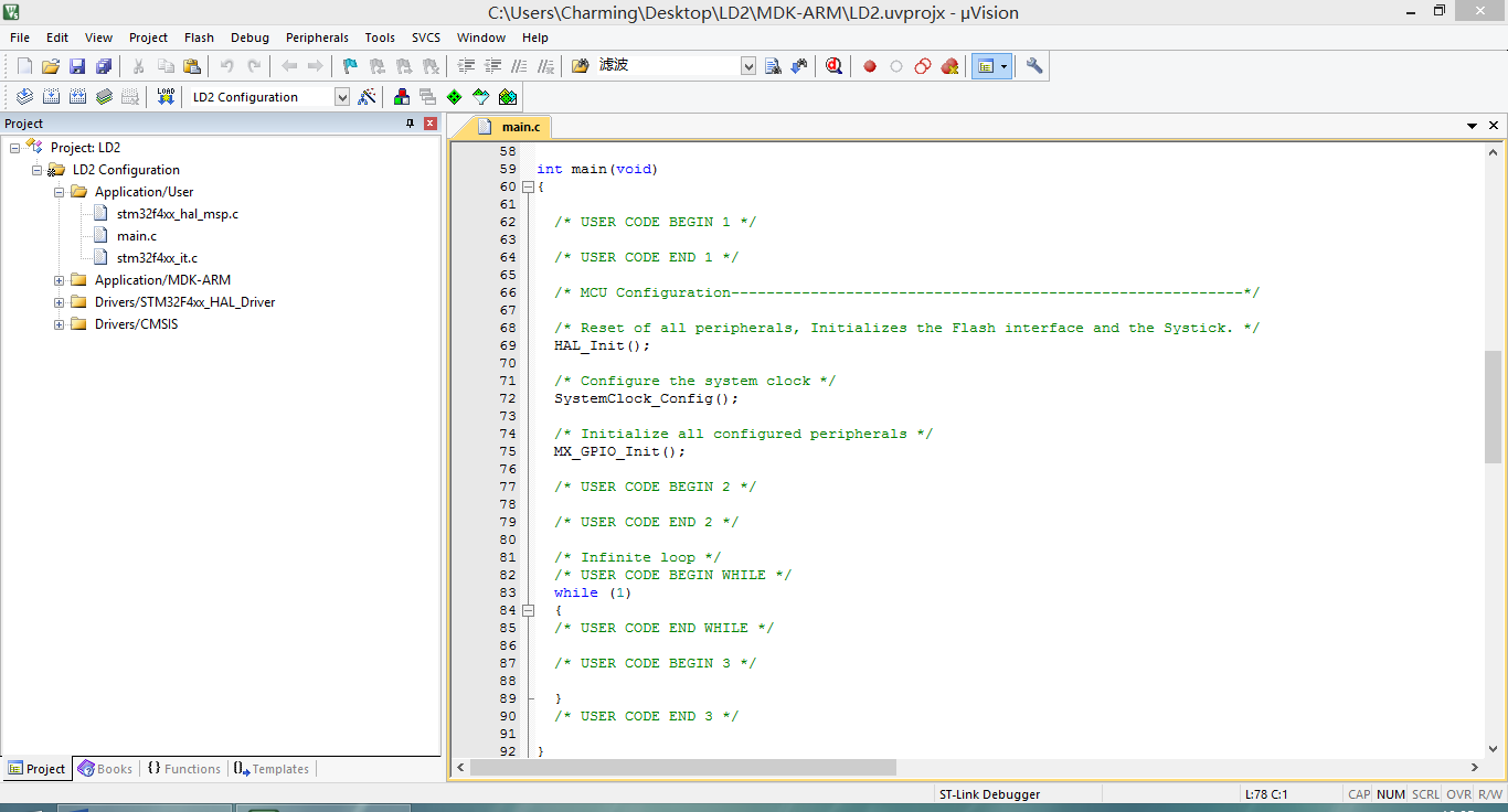
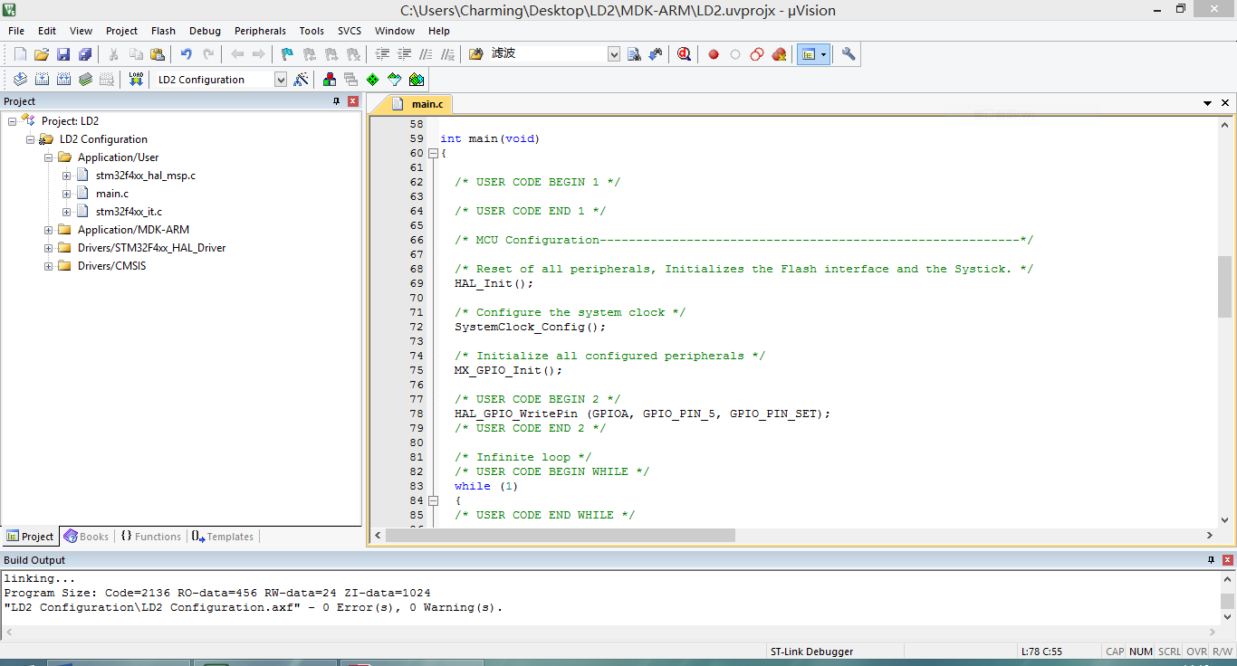
Open the Keil project and find the place to add code according to the comments. Please do not add code outside the prompt, otherwise it will be deleted when you generate the STM32CubeMX project again: (Because STM32CubeMX has generated the initialization code for us, we only need to add a sentence between /* USER CODE BEGIN 2 / and / USER CODE END 2 */ to make PA5 output high level)
Open the HAL driver manual to find the API we need, and then add code according to the instructions: (According to the instructions, the code to make PA5 output high level is HAL_GPIO_WritePin (GPIOA, GPIO_PIN_5, GPIO_PIN_SET);) 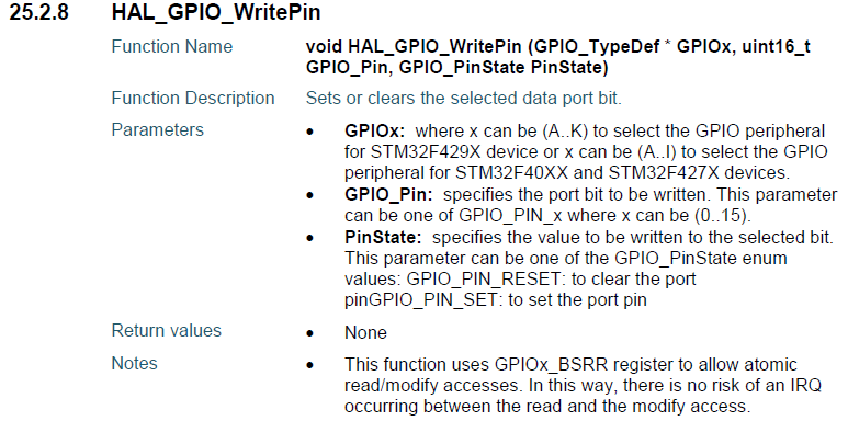
Add code to the project, then click 

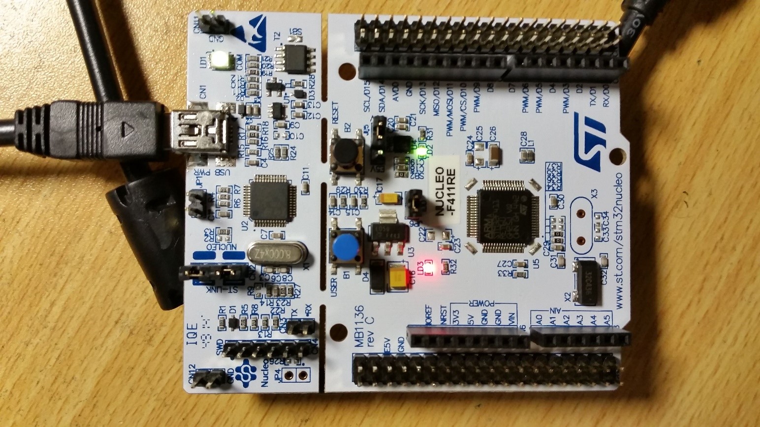
5. After the download is complete, reset the development board, and then the LD2 (green light) of the development board lights up.
Previous article:In-depth understanding of STM32 memory and bus architecture 1 (based on STM32F411)
Next article:Getting Started Tutorial Using HAL Library, STM32CubeMX and Keil 5 Development (Part 2): GPIO
- Popular Resources
- Popular amplifiers
- Learn ARM development(16)
- Learn ARM development(17)
- Learn ARM development(18)
- Embedded system debugging simulation tool
- A small question that has been bothering me recently has finally been solved~~
- Learn ARM development (1)
- Learn ARM development (2)
- Learn ARM development (4)
- Learn ARM development (6)
 Professor at Beihang University, dedicated to promoting microcontrollers and embedded systems for over 20 years.
- LED chemical incompatibility test to see which chemicals LEDs can be used with
- Application of ARM9 hardware coprocessor on WinCE embedded motherboard
- What are the key points for selecting rotor flowmeter?
- LM317 high power charger circuit
- A brief analysis of Embest's application and development of embedded medical devices
- Single-phase RC protection circuit
- stm32 PVD programmable voltage monitor
- Introduction and measurement of edge trigger and level trigger of 51 single chip microcomputer
- Improved design of Linux system software shell protection technology
- What to do if the ABB robot protection device stops
- CGD and Qorvo to jointly revolutionize motor control solutions
- CGD and Qorvo to jointly revolutionize motor control solutions
- Keysight Technologies FieldFox handheld analyzer with VDI spread spectrum module to achieve millimeter wave analysis function
- Infineon's PASCO2V15 XENSIV PAS CO2 5V Sensor Now Available at Mouser for Accurate CO2 Level Measurement
- Advanced gameplay, Harting takes your PCB board connection to a new level!
- Advanced gameplay, Harting takes your PCB board connection to a new level!
- A new chapter in Great Wall Motors R&D: solid-state battery technology leads the future
- Naxin Micro provides full-scenario GaN driver IC solutions
- Interpreting Huawei’s new solid-state battery patent, will it challenge CATL in 2030?
- Are pure electric/plug-in hybrid vehicles going crazy? A Chinese company has launched the world's first -40℃ dischargeable hybrid battery that is not afraid of cold
- Ubuntu development environment installation (I) system installation
- Implementation strategies for Industrial IoT networks
- The long-lasting coronavirus
- XXXXX Teardown
- Working principle and application of module power supply
- RF/Wireless Popular Data Download Collection
- How to implement wireless video transmission
- [Me and Atria 3] at32-littlevgl uses gui-guider designer to make a mini-hmi display
- Come if you dare! Enter the top-secret black technology laboratory of Tektronix!
- How to read the varistor data sheet? From related terms to component selection

 5962-9312901M2X


 京公网安备 11010802033920号