/****************************************************************
Function: OnePulse_GPIO_Init
Description: Timer pin initialization
Input: none
return: none
**********************************************************/
static void OnePulse_GPIO_Init(void)
{
GPIO_InitTypeDef GPIO_InitStructure;
RCC_APB2PeriphClockCmd(RCC_APB2Periph_GPIOB, ENABLE);
GPIO_InitStructure.GPIO_Pin = GPIO_Pin_6; //The pin corresponding to TIM4 CH1 is configured as multiplexed output
GPIO_InitStructure.GPIO_Mode = GPIO_Mode_AF_PP;
GPIO_InitStructure.GPIO_Speed = GPIO_Speed_50MHz;
GPIO_Init(GPIOB, &GPIO_InitStructure);
GPIO_InitStructure.GPIO_Pin = GPIO_Pin_7; //Configure the pin corresponding to TIM4 CH2 as floating input
GPIO_InitStructure.GPIO_Mode = GPIO_Mode_IN_FLOATING;
GPIO_Init(GPIOB, &GPIO_InitStructure);
}
/****************************************************************
Function: OnePulse_TIM4_Init
Description: Timer 4 configuration
Input: none
return: none
**********************************************************/
static void OnePulse_TIM4_Init(void)
{
TIM_TimeBaseInitTypeDef TIM_TimeBaseStructure;
TIM_ICInitTypeDef TIM_ICInitStructure;
TIM_OCInitTypeDef TIM_OCInitStructure;
RCC_APB1PeriphClockCmd(RCC_APB1Periph_TIM4, ENABLE);//Initialize TIM4 clock
/*---------------------------------------------------------
The timing base of TIM4 is 1/(72M/72)=1us.
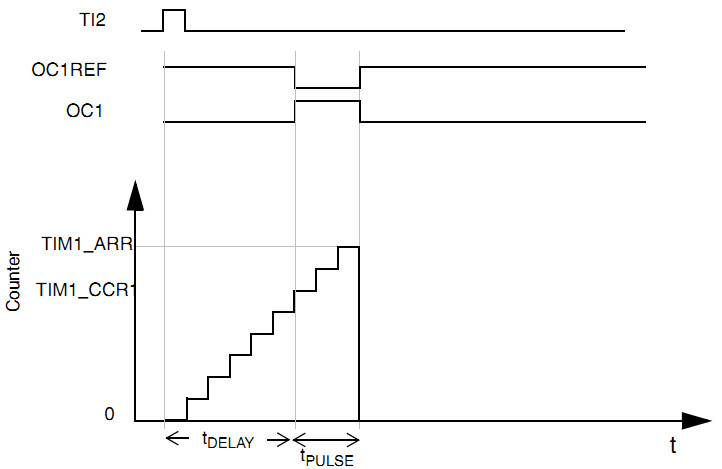
CH1 of TIM4 is configured as PWM2 output mode, and CH2 of TIM4 is configured as input capture mode.
In PWM2 mode, when the count value is less than the comparison value, it is an invalid level, i.e., a low level.
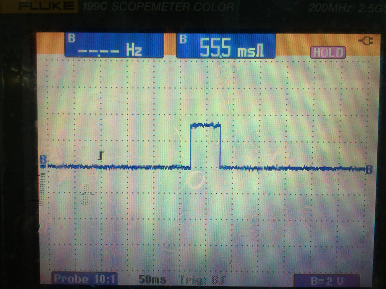
After TIM2 CH2 detects a rising edge, it outputs a pulse after a certain delay time.
The delay time = 10000 * 1us = 10ms
and the pulse width = (65535 - 10000) * 1us = 65.535ms.
---------------------------------------------------------*/
TIM_TimeBaseStructure.TIM_Period = 65535;//Timer period valueTIM_TimeBaseStructure.TIM_Prescaler
= 72 - 1;//PrescalerTIM_TimeBaseStructure.TIM_ClockDivision
= 0;//Clock not dividedTIM_TimeBaseStructure.TIM_CounterMode
= TIM_CounterMode_Up;//Up counting modeTIM_TimeBaseInit
(TIM4, &TIM_TimeBaseStructure);//Initialize timer time baseTIM_OCInitStructure.TIM_OCMode
= TIM_OCMode_PWM2;//TIM4 CH1 is configured as PWM2 output modeTIM_OCInitStructure.TIM_OutputState
= TIM_OutputState_Enable;//Output enableTIM_OCInitStructure.TIM_Pulse
= 10000;//Set the jump valueTIM_OCInitStructure.TIM_OCPolarity
= TIM_OCPolarity_High;//The effective level is highTIM_OC1Init
(TIM4, &TIM_OCInitStructure);
TIM_ICStructInit(&TIM_ICInitStructure);//Initialize the input capture structureTIM_ICInitStructure.TIM_Channel
= TIM_Channel_2;//TIM4 CH2 is configured as input capture modeTIM_ICInitStructure.TIM_ICPolarity
= TIM_ICPolarity_Rising;//Rising edge captureTIM_ICInitStructure.TIM_ICSelection
= TIM_ICSelection_DirectTI;//Direct correspondence between management and registersTIM_ICInitStructure.TIM_ICPrescaler
= TIM_ICPSC_DIV1; //Not with frequency division
TIM_ICInitStructure.TIM_ICFilter = 0; //No filtering
TIM_ICInit(TIM4, &TIM_ICInitStructure); //Initialize TIM4 CH2
TIM_SelectOnePulseMode(TIM4, TIM_OPMode_Single); //Select timer as single pulse mode
TIM_SelectInputTrigger(TIM4, TIM_TS_TI2FP2); //Select trigger source as IC2
TIM_SelectSlaveMode(TIM4, TIM_SlaveMode_Trigger); //Select timer slave mode as rising edge trigger
}
/****************************************************************
Function: OnePulse_Init
Description: Single pulse mode initialization
Input: none
return: none
*************************************************************/
void OnePulse_Init(void)
{
OnePulse_GPIO_Init();
OnePulse_TIM4_Init();
}
#ifndef __ONEPULSE_H__
#define __ONEPULSE_H__
#include "stm32f10x.h"
void OnePulse_Init(void);
#endif
/****************************************************** ************
Function: main
Description: mainInput
: none
return: none
************************* ************************************/
int main(void)
{
BSP_Init();
OnePulse_Init() ;
PRINTF("\nmain() is running!\r\n");
while(1)
{
LED1_Toggle();
Delay_ms(1000);
}
}


Previous article:STM32 six-step PWM output
Next article:STM32 timer output compare flip mode
- Popular Resources
- Popular amplifiers
- Learn ARM development(16)
- Learn ARM development(17)
- Learn ARM development(18)
- Embedded system debugging simulation tool
- A small question that has been bothering me recently has finally been solved~~
- Learn ARM development (1)
- Learn ARM development (2)
- Learn ARM development (4)
- Learn ARM development (6)
 Professor at Beihang University, dedicated to promoting microcontrollers and embedded systems for over 20 years.
- LED chemical incompatibility test to see which chemicals LEDs can be used with
- Application of ARM9 hardware coprocessor on WinCE embedded motherboard
- What are the key points for selecting rotor flowmeter?
- LM317 high power charger circuit
- A brief analysis of Embest's application and development of embedded medical devices
- Single-phase RC protection circuit
- stm32 PVD programmable voltage monitor
- Introduction and measurement of edge trigger and level trigger of 51 single chip microcomputer
- Improved design of Linux system software shell protection technology
- What to do if the ABB robot protection device stops
- Analysis of the application of several common contact parts in high-voltage connectors of new energy vehicles
- Wiring harness durability test and contact voltage drop test method
- From probes to power supplies, Tektronix is leading the way in comprehensive innovation in power electronics testing
- From probes to power supplies, Tektronix is leading the way in comprehensive innovation in power electronics testing
- Sn-doped CuO nanostructure-based ethanol gas sensor for real-time drunk driving detection in vehicles
- Design considerations for automotive battery wiring harness
- Do you know all the various motors commonly used in automotive electronics?
- What are the functions of the Internet of Vehicles? What are the uses and benefits of the Internet of Vehicles?
- Power Inverter - A critical safety system for electric vehicles
- Analysis of the information security mechanism of AUTOSAR, the automotive embedded software framework
- Overview of multi-string battery protection chip manufacturers
- Implementation of PID Control Algorithm Based on DSP
- Confused about measuring tantalum capacitors with a digital multimeter?
- This year, friends in the RF field, please come and discuss.
- 【National Technology N32G430】Review of lighting up WS2812 lamp
- 【Silicon Labs BG22-EK4108A Bluetooth Development Review】EFRConnect Mobile Applicationw and Issues
- kicad-age_12-layer_ciaa_acc
- Goodbye 2019, Hello 2020 + Standing at the Crossroads of Life
- Application of FPGA in barcode reader.zip
- 【GD32307E-START】02-Drawing of mechanical dimension drawings

 TS27L4BMPT


 京公网安备 11010802033920号