/****************************************************************
Function: TriangleWave_GPIO_Init
Description: Initialize the pin corresponding to the triangle wave
Input: none
return: none
**********************************************************/
static void TriangleWave_GPIO_Init(void)
{
GPIO_InitTypeDef GPIO_InitStructure;
RCC_APB2PeriphClockCmd(RCC_APB2Periph_GPIOA, ENABLE);//Initialize the pin clock
GPIO_InitStructure.GPIO_Pin = GPIO_Pin_4 | GPIO_Pin_5;//Initialize the pins corresponding to CH1 and CH2 of DAC
GPIO_InitStructure.GPIO_Mode = GPIO_Mode_AIN;//Analog input
GPIO_Init(GPIOA, &GPIO_InitStructure);
}
/****************************************************************
Function: TriangleWave_TIM_Init
Description: Timer initialization required for three-foot wave
Input: none
return: none
**************************************************************/
static void TriangleWave_TIM_Init(void)
{
TIM_TimeBaseInitTypeDef TIM_TimeBaseStructure;
RCC_APB1PeriphClockCmd(RCC_APB1Periph_TIM2, ENABLE);//Initialize TIM2 clock
TIM_TimeBaseStructInit(&TIM_TimeBaseStructure);//Initialize time base structure
TIM_TimeBaseStructure.TIM_Period = 100;//Period value is 100
TIM_TimeBaseStructure.TIM_Prescaler = 0;//No pre-division
TIM_TimeBaseStructure.TIM_ClockDivision = 0x0; //Clock is not divided
TIM_TimeBaseStructure.TIM_CounterMode = TIM_CounterMode_Up; //Count up
TIM_TimeBaseInit(TIM2, &TIM_TimeBaseStructure); //Initialize TIM2
TIM_SelectOutputTrigger(TIM2, TIM_TRGOSource_Update); //Set the trigger source to update trigger, update cycle once, then trigger a DAC conversion
TIM_Cmd(TIM2, ENABLE); //Turn on the timer
}
/****************************************************************
Function: TriangleWave_DAC_Init
Description: DAC initialization required for triangle wave
Input: none
return: none
**********************************************************/
static void TriangleWave_DAC_Init(void)
{
DAC_InitTypeDef DAC_InitStructure;
RCC_APB1PeriphClockCmd(RCC_APB1Periph_DAC, ENABLE);//Initialize DAC clock
DAC_InitStructure.DAC_Trigger = DAC_Trigger_T2_TRGO;//DAC trigger source is TIM2
DAC_InitStructure.DAC_WaveGeneration = DAC_WaveGeneration_Triangle;//Output triangle wave
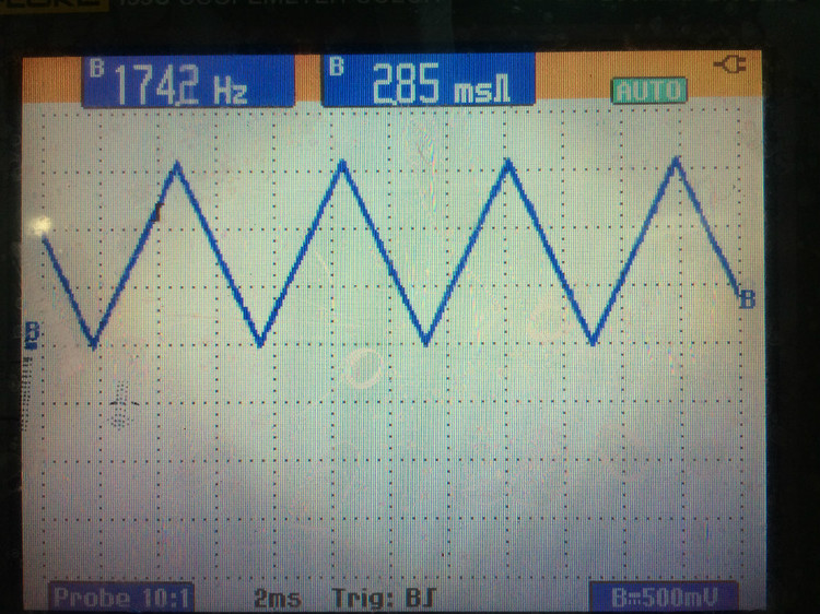
DAC_InitStructure.DAC_LFSRUnmask_TriangleAmplitude = DAC_TriangleAmplitude_2047;//The digital value corresponding to the amplitude of the triangle wave is 2047, that is, 1.65V, and the frequency is about 72M/100/2048/2=175Hz (a little different from the actual output frequency)
DAC_InitStructure.DAC_OutputBuffer = DAC_OutputBuffer_Disable;//DAC output buffer is not applicable
DAC_Init(DAC_Channel_1, &DAC_InitStructure);//Initialize DAC CH1
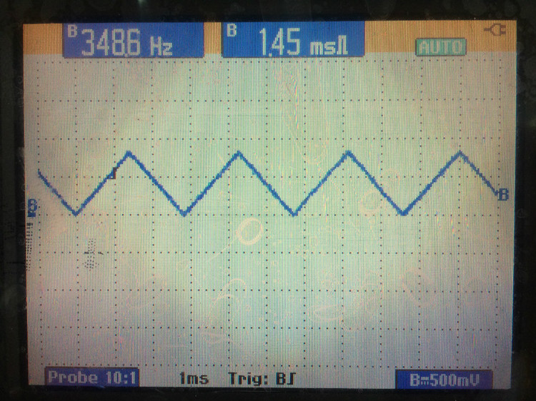
DAC_InitStructure.DAC_LFSRUnmask_TriangleAmplitude = DAC_TriangleAmplitude_1023;//The digital value corresponding to the amplitude of the triangle wave is 1023, that is, 0.825V, and the frequency is about 72M/100/1024/2=252Hz (a little different from the actual output frequency)
DAC_Init(DAC_Channel_2, &DAC_InitStructure);//Initialize DAC CH2
DAC_Cmd(DAC_Channel_1, ENABLE);//Turn on DAC CH1
DAC_Cmd(DAC_Channel_2, ENABLE);//Turn on DAC CH2
DAC_SetDualChannelData(DAC_Align_12b_R, 0x00, 0x00);//Set the data of the two DAC channels to right align, and the digital quantity corresponding to the trough is 0,0
}
/****************************************************************
Function: TriangleWave_Init
Description: Triangle wave initialization
Input: none
return: none
**************************************************************/
void TriangleWave_Init(void)
{
TriangleWave_GPIO_Init();
TriangleWave_TIM_Init();
TriangleWave_DAC_Init();
}
#ifndef __TRIANGLEWAVE_H__
#define __TRIABGLEWAVE_H__
#include "stm32f10x.h"
void TriangleWave_Init(void);
#endif
/****************************************************** ************
Function: main
Description: mainInput
: none
return: none
************************* **********************************/
int main(void)
{
BSP_Init();
TriangleWave_Init() ;
PRINTF("\nmain() is running!\r\n");
while(1)
{
LED1_Toggle();
Delay_ms(1000);
}
}


Previous article:STM32 serial port DMA transmission
Next article:STM32 step wave output
Recommended ReadingLatest update time:2024-11-22 22:18


- Popular Resources
- Popular amplifiers
- Naxin Micro and Xinxian jointly launched the NS800RT series of real-time control MCUs
- How to learn embedded systems based on ARM platform
- Summary of jffs2_scan_eraseblock issues
- Application of SPCOMM Control in Serial Communication of Delphi7.0
- Using TComm component to realize serial communication in Delphi environment
- Bar chart code for embedded development practices
- Embedded Development Learning (10)
- Embedded Development Learning (8)
- Embedded Development Learning (6)
 Professor at Beihang University, dedicated to promoting microcontrollers and embedded systems for over 20 years.
- Intel promotes AI with multi-dimensional efforts in technology, application, and ecology
- ChinaJoy Qualcomm Snapdragon Theme Pavilion takes you to experience the new changes in digital entertainment in the 5G era
- Infineon's latest generation IGBT technology platform enables precise control of speed and position
- Two test methods for LED lighting life
- Don't Let Lightning Induced Surges Scare You
- Application of brushless motor controller ML4425/4426
- Easy identification of LED power supply quality
- World's first integrated photovoltaic solar system completed in Israel
- Sliding window mean filter for avr microcontroller AD conversion
- What does call mean in the detailed explanation of ABB robot programming instructions?
- STMicroelectronics discloses its 2027-2028 financial model and path to achieve its 2030 goals
- 2024 China Automotive Charging and Battery Swapping Ecosystem Conference held in Taiyuan
- State-owned enterprises team up to invest in solid-state battery giant
- The evolution of electronic and electrical architecture is accelerating
- The first! National Automotive Chip Quality Inspection Center established
- BYD releases self-developed automotive chip using 4nm process, with a running score of up to 1.15 million
- GEODNET launches GEO-PULSE, a car GPS navigation device
- Should Chinese car companies develop their own high-computing chips?
- Infineon and Siemens combine embedded automotive software platform with microcontrollers to provide the necessary functions for next-generation SDVs
- Continental launches invisible biometric sensor display to monitor passengers' vital signs
- What is the relationship between STM32 and IoT?
- How to make aluminum conductors contact firmly
- About the status of STC microcontroller IO port
- Nand flash driver working principle
- Several questions in the chip manual
- Southchip SC8905 EVM evaluation report summary
- There is a new board~~ Take a look~~
- LSM6DSOX First Experience
- About CC2640 power consumption test problem
- An experienced person tells you how to choose a common mode noise filter

 usb_host_device_code
 Transplantation of real-time operating system RT-ThreadSmart on STM32MP1


 京公网安备 11010802033920号