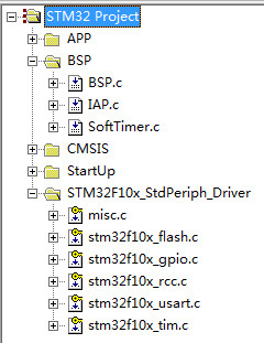
/****************************************************************
Function: IAP_Init
Description: IAP initialization function, initialize serial port 1
Input: none
return: none
**********************************************************/
void IAP_Init(void)
{
GPIO_InitTypeDef GPIO_InitStructure;
USART_InitTypeDef USART_InitStructure;
NVIC_InitTypeDef NVIC_InitStructure;
RCC_APB2PeriphClockCmd(COM1_RCC, ENABLE);//Enable USART1 clock
RCC_APB2PeriphClockCmd(COM1_GPIO_RCC, ENABLE);//Enable serial port 2 pin clock
GPIO_InitStructure.GPIO_Mode = GPIO_Mode_AF_PP;//Configure USART1 Tx The pin type is push-pull
GPIO_InitStructure.GPIO_Pin = COM1_TX_PIN;
GPIO_InitStructure.GPIO_Speed = GPIO_Speed_50MHz;
GPIO_Init(COM1_GPIO_PORT, &GPIO_InitStructure);
GPIO_InitStructure.GPIO_Mode = GPIO_Mode_IN_FLOATING; //Configure USART1's Rx as input floating
GPIO_InitStructure.GPIO_Pin = COM1_RX_PIN;
GPIO_Init(COM1_GPIO_PORT, &GPIO_InitStructure);
USART_InitStructure.USART_BaudRate = 115200; //Set the baud rate to 115200
USART_InitStructure.USART_WordLength = USART_WordLength_8b;//Set data bits to 8 bitsUSART_InitStructure.USART_StopBits
= USART_StopBits_1;//Set stop bit to 1 bitUSART_InitStructure.USART_Parity
= USART_Parity_No;//No parity checkUSART_InitStructure.USART_HardwareFlowControl
= USART_HardwareFlowControl_None;//No hardware flow controlUSART_InitStructure.USART_Mode
= USART_Mode_Rx | USART_Mode_Tx;//Send and receiveUSART_ITConfig
(COM1, USART_IT_RXNE, ENABLE);//Receive interrupt enableUSART_Init
(COM1,&USART_InitStructure);//Configure serial port 2 related registersUSART_Cmd
(COM1,ENABLE); //Enable serial port 2
NVIC_InitStructure.NVIC_IRQChannel = USART1_IRQn; //Channel is set to serial port 2 interrupt
NVIC_InitStructure.NVIC_IRQChannelSubPriority = 0; //Interrupt occupies priority 0
NVIC_InitStructure.NVIC_IRQChannelCmd = ENABLE; //Enable interrupt
NVIC_Init(&NVIC_InitStructure);
}
/****************************************************************
Function: IAP_SerialSendByte
Description: Serial port sends byte
Input: c-byte to be sent
Return: none
**************************************************************/
static void IAP_SerialSendByte(u8 c)
{
USART_SendData(COM1, c);
while (USART_GetFlagStatus(COM1, USART_FLAG_TXE) == RESET) {}
}
/*****************************************************************
Function: IAP_SerialSendStr
Description: Serial port sends string
Input: none
Return: none
*************************************************************/
void IAP_SerialSendStr(u8 *s)
{
while(*s != '\0')
{
IAP_SerialSendByte(*s);
s++;
}
}
#define MAXBUFFER 512 //buffer size
u8 UsartBuffer[MAXBUFFER]; //data buffer
u16 UsartWptr = 0;
u16 UsartRptr = 0;
/****************************************************************
Function: IAP_BufferWrite
Description: Write buffer
Input: none
return: none
**********************************************************/
void IAP_BufferWrite(void)
{
if(UsartWptr == (UsartRptr - 1))//The buffer is full
{
return;//Return
}
UsartBuffer[UsartWptr] = USART_ReceiveData(COM1);//Access serial port data
UsartWptr++;//Buffer write position value increments
UsartWptr = UsartWptr%MAXBUFFER;//Ensure that the write position value does not overflow
}
/*****************************************************************
Function: IAP_BufferRead
Description: Read buffer
Input: none
return: none
*****************************************************************/
static u8 IAP_BufferRead(u8 *data)
{
if(UsartRptr == UsartWptr)//No data to read
{
return 0;
}
*data = UsartBuffer[UsartRptr];//Read buffer data
UsartRptr++;//Read position value increments
UsartRptr = UsartRptr % MAXBUFFER;//Ensure that the read position value does not overflow
return 1;
}
/****************************************************** ************
Function: IAP_ShowMenu
Description: Display menu interface
Input: none
return: none
************************ *************************************/
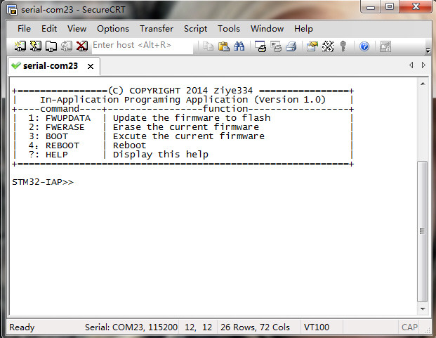
void IAP_ShowMenu(void)
{
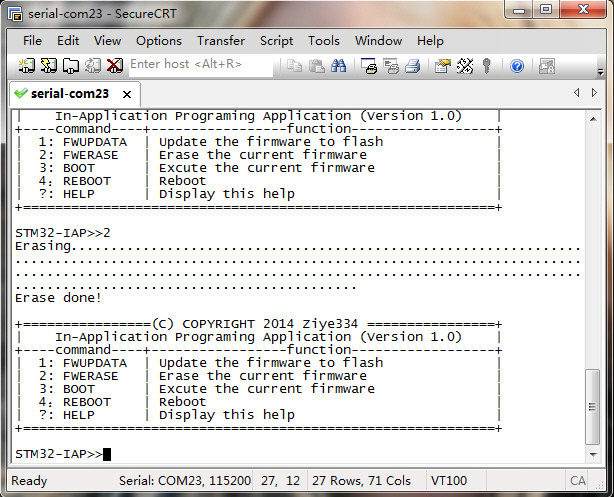
IAP_SerialSendStr("\r\ n+================(C) COPYRIGHT 2014 Ziye334 ================+");
IAP_SerialSendStr("\r\n | In-Application Programing Application (Version 1.0) |");
IAP_SerialSendStr("\r\n+----command----+-----------------function- ------------------+");
IAP_SerialSendStr("\r\n| 1: FWUPDATA | Update the firmware to flash |");
IAP_SerialSendStr("\r\n| 2: FWERASE | Erase the current firmware |");
IAP_SerialSendStr("\r\n| 3: BOOT | Excute the current firmware |");
IAP_SerialSendStr("\r\n| 4: REBOOT | Reboot |");
IAP_SerialSendStr(" \r\n| ?: HELP | Display this help |");
IAP_SerialSendStr("\r\n+============================ ================================+");
IAP_SerialSendStr("\r\n\r\n");
IAP_SerialSendStr("STM32-IAP>>");
}
extern u8 rcvTimeout; //Receive timeout flag
/****************************************************************
Function: IAP_UpdataProgram
Description: Update program
Input: none
Return: none
**********************************************************/
static void IAP_UpdataProgram(void)
{
u8 blockNum = 0; //Block, 4 pages per block, for STM32F10X_HD, 1 page is 2Kbytes
u8 n = 0;
u8 data = 0;
u8 datalow = 0;
u8 datahigh = 0;
u32 UserMemoryMask = 0;
rcvTimeout = 0; //Clear receive timeout flag
blockNum = (IAP_ADDR - FLASH_BASE_ADDR) >> 12; //Calculate flash block
UserMemoryMask = ((u32)(~((1 << blockNum) - 1))); //Calculate the mask
//Check whether the area where the block is located is write protected
if((FLASH_GetWriteProtectionOptionByte() & UserMemoryMask) != UserMemoryMask)
{
FLASH_EraseOptionBytes (); //Turn off write protection
}
while(1)
{
switch(n)
{
case 0:
if(IAP_BufferRead(&data)) //Receive ground byte data
{
datalow = data;
n = 1;
}
else
{
break;
}
case 1:
if(IAP_BufferRead(&data)) //Receive high byte data
{
datahigh = data;
n = 0;
IAP_FlashProgramdata(((u16)(datalow)) | ((u16)(datahigh << 8)));
}
if(rcvTimeout) //Receive timeout, error or end of receive
{
datahigh = 0xff;
n = 0;
IAP_FlashProgramdata(((u16)(datalow)) | ((u16)(datahigh << 8)));
}
default:
break;
}
if(rcvTimeout)//Receive timeout
{
break;
}
}
}
/****************************************************************
Function: IAP_FlashProgramdata
Description: Burn data
Input: data-data to be burned
Return: none
*************************************************************/
static void IAP_FlashProgramdata(u16 data)
{
static u32 flashwptr = IAP_ADDR;
FLASH_Unlock();//flash lock
FLASH_ClearFlag(FLASH_FLAG_EOP | FLASH_FLAG_PGERR | FLASH_FLAG_WRPRTERR);//clear flash related flags
FLASH_ProgramHalfWord(flashwptr, data); //burn half word data
if(flashwptr == IAP_ADDR)//start burning
{
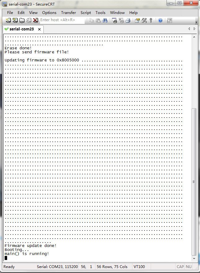
IAP_SerialSendStr("\r\nUpdating firmware to 0x8005000 ");
}
IAP_SerialSendStr("."); //Show the burning process
flashwptr = flashwptr + 2; //Move the burning address
FLASH_Lock(); //Flash unlock
}
/****************************************************************
Function: IAP_FlashEease
Description: Erase Flash
Input: none
return: none
**********************************************************/
static void IAP_FlashEease(void)
{
u16 eraseCounter = 0;
u16 nbrOfPage = 0;
nbrOfPage = (FLASH_BASE_ADDR + FLASH_SIZE - IAP_ADDR)/PAGE_SIZE;//Calculate the number of pages
FLASH_Unlock(); //Release flash erase and write lock
FLASH_ClearFlag(FLASH_FLAG_EOP | FLASH_FLAG_PGERR | FLASH_FLAG_WRPRTERR);//Clear flash related flags
for(eraseCounter = 0; eraseCounter < nbrOfPage; eraseCounter++)//Start erasing
{
IAP_SerialSendStr(".");//Display progress
FLASH_ErasePage(IAP_ADDR + (eraseCounter * PAGE_SIZE));//Erase
}
FLASH_Lock();//Flash erase and write lock
}
typedef void (*pFunction)(void);
pFunction Jump_To_Application;
u32 JumpAddress; //jump address
/****************************************************************
Function: IAP_JumpToApplication
Description: Jump to the upgrade program
Input: none
return: none
**********************************************************/
void IAP_JumpToApplication(void)
{
if(((*(__IO u32 *)IAP_ADDR) & 0x2FFE0000) == 0x20000000)//There is an upgrade code, the IAP_ADDR address processing should point to the main stack area, that is, 0x20000000
{
JumpAddress = *(__IO u32 *)(IAP_ADDR + 4);//Get the reset address
Jump_To_Application = (pFunction)JumpAddress;//The function pointer points to the reset address
__set_MSP(*(__IO u32*)IAP_ADDR);//Set the main stack pointer MSP to point to the upgrade mechanism IAP_ADDR
Jump_To_Application(); // Jump to the upgrade code
}
}
/****************************************************** ************
Function: ShwHelpInfo
Description: Display help information
Input: none
return: none
************************ *************************************/
static void ShwHelpInfo(void)
{
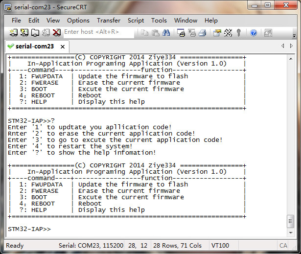
IAP_SerialSendStr("\r \nEnter '1' to update you apllication code!");
IAP_SerialSendStr("\r\nRnter '2' to erase the current application code!");
IAP_SerialSendStr("\r\nEnter '3' to go to excute the current application code!");
IAP_SerialSendStr("\r\nEnter '4' to restart the system!");
IAP_SerialSendStr("\r\nEnter '?' to show the help infomation!\r\n");
}
/****************************************************************
Function: IAP_GetKey
Description: Get the input value
Input: none
return: Return the key value
******************************************************************/
static u8 IAP_GetKey(void)
{
u8 data;
while(!IAP_BufferRead(&data)){}//Get the key value from the buffer
return data;
}
/****************************************************************
Function: IAP_WiatForChoose
Description: Function selection
Input: none
return: none
*************************************************************/
void IAP_WiatForChoose(void)
{
u8 c = 0;
while (1)
{
c = IAP_GetKey();//Get key value
IAP_SerialSendByte(c);//Serial port returns key value
switch(c)
{
case '1': //FWUPDATA firmware upgrade
if((IAP_GetKey() == '\r'))//Detect enter key
{
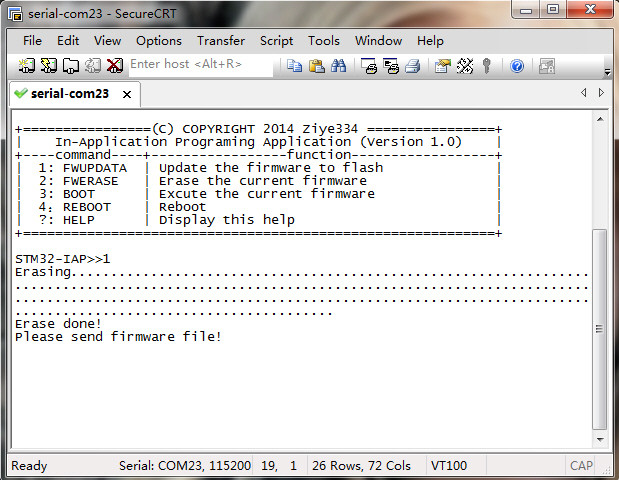
IAP_SerialSendStr("\r\nErasing...");
IAP_FlashEease();//Erase Flash
IAP_SerialSendStr("\r\nErase done!\r\n");
IAP_SerialSendStr("Please send firmware file!\r\n");
IAP_UpdataProgram();//Burn the upgrade code
IAP_SerialSendStr("\r\nFirmware update done!\r\n");
IAP_SerialSendStr("Booting...\r\n");
Delay_ms(500);
NVIC_SystemReset();//Restart
}
break;
case '2'://FWERASE firmware erase
if((IAP_GetKey() == '\r'))//Detect the enter key
{
IAP_SerialSendStr("\r\nErasing...");
IAP_FlashEease();//Erase Flash
IAP_SerialSendStr("\r\nErase done!\r\n");
return;//Exit the loop
}
break;
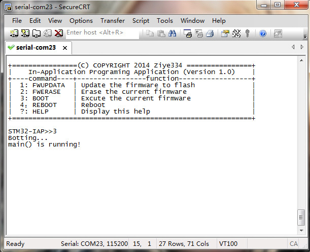
case '3'://BOOT execute the upgrade program
if((IAP_GetKey() == '\r'))
{
IAP_SerialSendStr("\r\nBotting...\r\n");
if(((*(__IO u32 *)IAP_ADDR) & 0x2FFE0000) != 0x20000000)
{
IAP_SerialSendStr("No user program! Please download a firmware!\r\n");
}
Delay_ms(500);
NVIC_SystemReset();
return;//Exit the loop
}
break;
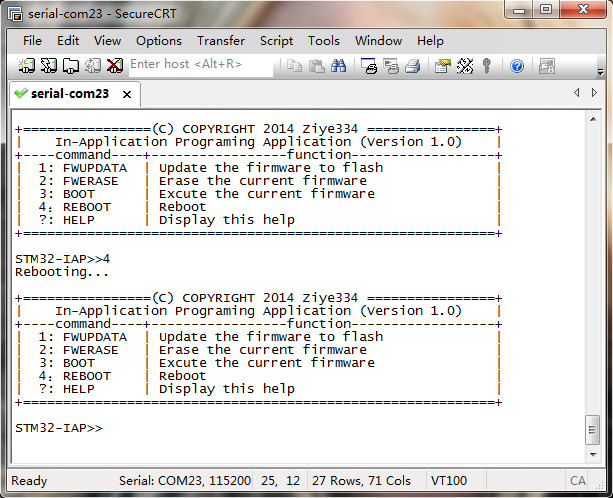
case '4'://REBOOT system restart
if((IAP_GetKey() == '\r'))//Detect the enter key
{
IAP_SerialSendStr("\r\nRebooting...\r\n");
return;//Exit the loop
}
break;
case '?'://HELP help
if((IAP_GetKey() == '\r'))
{
ShwHelpInfo();//Display help information
return;//Exit the loop
}
break;
default:
IAP_SerialSendStr("\r\nInvalid Number! The number should be either 1, 2, 3, 4or5\r\n");
return;//Exit the loop
}
}
}
#ifndef __IAP_H__
#define __IAP_H__
#include "stm32f10x.h"
#define FLASH_BASE_ADDR 0x8000000 //Flash base address
#define IAP_ADDR 0x8005000 //Upgrade code address
#if defined (STM32F10X_MD) || defined (STM32F10X_MD_VL)
#define PAGE_ SIZE (0x400) / / 1 Kbyte
#define FLASH_SIZE (0x20000) // 128 KBytes
#elif defined STM32F10X_CL
#define PAGE_SIZE (0x800) // 2 Kbytes
#define FLASH_SIZE (0x40000) // 256 KBytes
#elif defined STM32F10X_HD || defined (STM32F10X_HD_VL)
#define PAGE_SIZE (0x800) // 2 Kbytes
#define FLASH_SIZE (0x80000) // 512 KBytes
#elif defined STM32F10X_XL
#define PAGE_SIZE (0x800) // 2 Kbytes
#define FLASH_SIZE (0x100000) // 1 M Byte
#else
# error "Please select first the STM32 device to be used (in stm32f10x.h)"
#endif
void IAP_Init(void);
void IAP_SerialSendStr(u8 *s);
void IAP_ShowMenu(void);
void IAP_WiatForChoose(void);
void IAP_BufferWrite(void );
void IAP_JumpToApplication(void);
#endif
/****************************************************************
Function: TIM2_IRQHandler
Description: Timer 2 interrupt service routine
Input: none
return: none
*************************************************************/
void TIM2_IRQHandler(void)
{
if(TIM_GetITStatus(TIM2, TIM_IT_Update) != RESET)
{
SoftTimer_TimerExecute();
TIM_ClearITPendingBit(TIM2, TIM_IT_Update);
}
}
/****************************************************************
Function: USART1_IRQHandler
Description: Serial port 1 interrupt service routine
Input: none
return: none
**********************************************************/
void USART1_IRQHandler(void)
{
if(USART_GetITStatus(USART1, USART_IT_RXNE) != RESET)//Detect receive interrupt flag
{
SoftTimer_TimerStart(0, 100, RcvTimeoutSet, (void*)0, TIMER_ONESHOT);//Start soft timer 1
IAP_BufferWrite();//Store received data
USART_ClearITPendingBit(USART1, USART_IT_RXNE); //Clear flag
}
}
u8 rcvTimeout = 0; //Receive timeout flag
/****************************************************************
Function: RcvTimeoutSet
Description: Serial port receiving data timeout
Input: parameter-parameter
return: none
*************************************************************/
void RcvTimeoutSet(void *parameter)
{
rcvTimeout = 1; //Set the receive timeout flag
}
/****************************************************** ************
Function: KeyInit
Description: Initialization key
Input: none
return: none
************************* ************************************/
void KeyInit (void)
{
GPIO_InitTypeDef GPIO_InitStructure;
RCC_APB2PeriphClockCmd(RCC_APB2Periph_GPIOA, ENABLE);
GPIO_InitStructure.GPIO_Pin = GPIO_Pin_8;
GPIO_InitStructure.GPIO_Mode = GPIO_Mode_IN_FLOATING;
GPIO_Init(GPIOA, &GPIO_InitStructure);
}
/************************** *************************************
Function: GetKey
Description: Get the key status
Input: none
return: none
* *************************************************** **********/
u8 GetKey (void)
{
return (GPIO_ReadInputDataBit(GPIOA, GPIO_Pin_8));
}
/****************************************************************
Function: main
Description: main entryInput
: none
return: none
**********************************************************/
int main(void)
{
BSP_Init();//Board initializationKeyInit
();//Initialize the keyif
(!GetKey())//Press the key to enter the upgrade interface
{
set: IAP_Init();//Initialize the serial
portSoftTimer_Init();//Initialize the soft timershw
: IAP_ShowMenu();//Show function
menuIAP_WiatForChoose(); //Wait for the selection interfacegoto
shw;//Redisplay the interface
}
else
{
IAP_JumpToApplication();//Jump to the upgrade code executiongoto
set;//This sentence will be executed only if there is no upgrade program or the upgrade program is wrong, and then jump to the upgrade interface
}
}
Previous article:Production of STM32 upgrade files
Next article:STM32 Multi-channel Soft Timer
- Popular Resources
- Popular amplifiers
- Naxin Micro and Xinxian jointly launched the NS800RT series of real-time control MCUs
- How to learn embedded systems based on ARM platform
- Summary of jffs2_scan_eraseblock issues
- Application of SPCOMM Control in Serial Communication of Delphi7.0
- Using TComm component to realize serial communication in Delphi environment
- Bar chart code for embedded development practices
- Embedded Development Learning (10)
- Embedded Development Learning (8)
- Embedded Development Learning (6)
 Professor at Beihang University, dedicated to promoting microcontrollers and embedded systems for over 20 years.
- Intel promotes AI with multi-dimensional efforts in technology, application, and ecology
- ChinaJoy Qualcomm Snapdragon Theme Pavilion takes you to experience the new changes in digital entertainment in the 5G era
- Infineon's latest generation IGBT technology platform enables precise control of speed and position
- Two test methods for LED lighting life
- Don't Let Lightning Induced Surges Scare You
- Application of brushless motor controller ML4425/4426
- Easy identification of LED power supply quality
- World's first integrated photovoltaic solar system completed in Israel
- Sliding window mean filter for avr microcontroller AD conversion
- What does call mean in the detailed explanation of ABB robot programming instructions?
- 2024 China Automotive Charging and Battery Swapping Ecosystem Conference held in Taiyuan
- State-owned enterprises team up to invest in solid-state battery giant
- The evolution of electronic and electrical architecture is accelerating
- The first! National Automotive Chip Quality Inspection Center established
- BYD releases self-developed automotive chip using 4nm process, with a running score of up to 1.15 million
- GEODNET launches GEO-PULSE, a car GPS navigation device
- Should Chinese car companies develop their own high-computing chips?
- Infineon and Siemens combine embedded automotive software platform with microcontrollers to provide the necessary functions for next-generation SDVs
- Continental launches invisible biometric sensor display to monitor passengers' vital signs
- Another technical solution for power-type plug-in hybrid: A brief discussion on Volvo T8 plug-in hybrid technology
- Virtual Parallel Oscilloscope
- Switching power supply design
- Gallium nitride substrate production technology and equipment
- Vivado generates IP core issues
- Safety temperature standards for main components of switching power supplies
- LabView Notes 1: Three methods based on LabView to implement the water lamp experiment
- Auxiliary trainer for plank and push-up exercises
- MicroPython will add serial port interrupt function
- MOS tube
- C6678 on-chip storage space allocation mechanism

 5962-89621012XA


 京公网安备 11010802033920号