IAP Program:


Keywords:STM32
Reference address:Solution to STM32 IAP not being able to run user programs
It mainly sets the starting address of the user program, APPLICATION_ADDRESS, such as 0x08004000, and writes the user code into the user area of FLASH through the peripheral. When the conditions are met, jump to the starting address of the user area.
Explain the jump code:
/* Test if user code is programmed starting from address "APPLICATION_ADDRESS" */
if (((*(__IO uint32_t*)APPLICATION_ADDRESS) & 0x2FFE0000 ) == 0x20000000) // Check if the stack top address is between 0x2000 0000 - 0x2000 2000
// Determine whether the user application has been downloaded by judging whether the stack top address value is correct. Because the user program startup file will initialize the stack space at the beginning, if the stack top address is correct, it means that the user program has been downloaded.
{
__set_PRIMASK(1); // Disable global interrupt. Note that global interrupt must be disabled before jumping. After entering the user program, enable interrupt after the interrupt vector table address is set.
printf("Jump to the new program.\r\n");
/* Jump to user application */
JumpAddress = *(__IO uint32_t*) (APPLICATION_ADDRESS + 4); // The first 4 bytes are the interrupt vector table
Jump_To_Application = (pFunction) JumpAddress; // Point to the address where the user program reset function is located
/* Initialize user application's Stack Pointer */
__set_MSP(*(__IO uint32_t*) APPLICATION_ADDRESS); // Set the stack pointer of the user program
Jump_To_Application(); // Execute user program
}
It should be noted that in the IAP program, the global interrupt needs to be disabled before jumping to the user program.
You can see the discussion on the forum http://www.amobbs.com/thread-5606964-1-1.html
User Program:
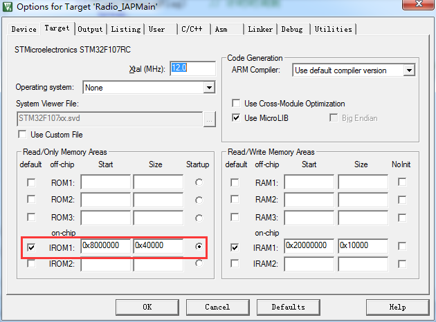
The main thing is to set the offset address of the interrupt vector table and the ROM start address in the project options. It should be noted that the interrupt vector table should be set after SystemInit(), and the global interrupt should be enabled.
The interrupt vector table can be set at the beginning of main.
Modification of project options

Add the part of setting the interrupt vector table at the beginning of the main function
//Use IAP to modify the base address of the user program area. It must be an integer multiple of 0x200 (stm32f205)
// Note: Modify the project options accordingly: IROM1: start: 0x8004000
#ifdef VECT_TAB_RAM
/* Set the Vector Table base location at 0x20000000 */
NVIC_SetVectorTable(NVIC_VectTab_RAM, 0x0);
#else /* VECT_TAB_FLASH */ // Modify the FLASH vector table, the starting address starts from 0x8004000 as the user program area
/* Set the Vector Table base location at 0x08000000 */
NVIC_SetVectorTable(NVIC_VectTab_FLASH, 0x4000);
__set_PRIMASK(0); // Enable global interrupt
#endif
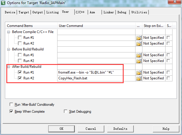
The user program needs to be converted to .bin format. In the project options, add fromelf.exe --bin -o "$L@L.bin" "#L" in User->After Build/Rebuild to output the bin file in the output directory.

You can also add a .bat file to copy the .hex and .bin files, for example:
copy ..\Objects\output.hex Flash\acq_v2_IAPMain.hex
copy ..\Objects\output.bin Flash\acq_v2_IAPMain.bin
Combined burning:
When burning the program, you need to use the burner to burn the IAP program first, which is the BOOTLOADER part, and then write the user program through the peripheral.
But in fact, these two steps can be combined into one step of burning.
Delete the last ending sentence of IAP's .hex file, that is, delete: 00000001FF; then copy all the contents of the user program's .hex file to the back of IAP's .hex file; finally, burn the integrated .hex file to the starting address of 0x0800 0000.
Previous article:STM32 ADC and DMA multi-channel processing
Next article:How to release pa15, pb3, pb4 as gpio ports in stm32
- Popular Resources
- Popular amplifiers
Recommended Content
Latest Microcontroller Articles
He Limin Column
Microcontroller and Embedded Systems Bible
 Professor at Beihang University, dedicated to promoting microcontrollers and embedded systems for over 20 years.
MoreSelected Circuit Diagrams
MorePopular Articles
- LED chemical incompatibility test to see which chemicals LEDs can be used with
- Application of ARM9 hardware coprocessor on WinCE embedded motherboard
- What are the key points for selecting rotor flowmeter?
- LM317 high power charger circuit
- A brief analysis of Embest's application and development of embedded medical devices
- Single-phase RC protection circuit
- stm32 PVD programmable voltage monitor
- Introduction and measurement of edge trigger and level trigger of 51 single chip microcomputer
- Improved design of Linux system software shell protection technology
- What to do if the ABB robot protection device stops
MoreDaily News
- Ranking of installed capacity of smart driving suppliers from January to September 2024: Rise of independent manufacturers and strong growth of LiDAR market
- Industry first! Xiaopeng announces P7 car chip crowdfunding is completed: upgraded to Snapdragon 8295, fluency doubled
- P22-009_Butterfly E3106 Cord Board Solution
- Keysight Technologies Helps Samsung Electronics Successfully Validate FiRa® 2.0 Safe Distance Measurement Test Case
- Innovation is not limited to Meizhi, Welling will appear at the 2024 China Home Appliance Technology Conference
- Innovation is not limited to Meizhi, Welling will appear at the 2024 China Home Appliance Technology Conference
- Huawei's Strategic Department Director Gai Gang: The cumulative installed base of open source Euler operating system exceeds 10 million sets
- Download from the Internet--ARM Getting Started Notes
- Learn ARM development(22)
- Learn ARM development(21)
Guess you like
- "English Abbreviations" in Hardware Schematics
- Very stuck, reinstall also stuck
- Convert PCB files from Cadence to PADS
- How does Qorvo build core barriers in the RF front end with the deep empowerment of 5G?
- How to determine whether the current file system is FAT or LittleFS format
- Latest K210 firmware (Loboris version)
- BLDC driver based on GD32
- The development board mounts the NFS server shared directory
- Origin of "Circuit Observation Room"
- Want to learn about Microchip PIC32MZ DA Disc Graphics Development Board? Welcome to sign up for the online seminar

 5962-8997401PA


 京公网安备 11010802033920号