1. Experimental task
: Use the table to make the port P1 change a single light: move left 2 times, move right 2 times, and flash 2 times (delay time 0.2 seconds).
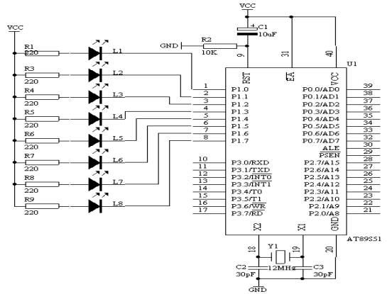
2. Circuit diagram

Figure 4.5.1
3. Hardware connection on the system board
Use an 8-core cable to connect P1.0-P1.7 in the "single-chip system" area to the L1-L8 ports in the "eight-way LED indicator module" area. The requirements are: P1.0 corresponds to L1, P1.1 corresponds to L2, ..., P1.7 corresponds to L8.
4. Program design content
When using a table for programming, the following instructions must be used to complete
(1).Use the instruction MOV DPTR, #DATA16 to make the data pointer register point to the beginning of the table.
(2).Use the instruction MOVC A, @A + DPTR, according to the value of the accumulator plus the value of DPTR, the program counter PC can be pointed to the data to be retrieved from the table.
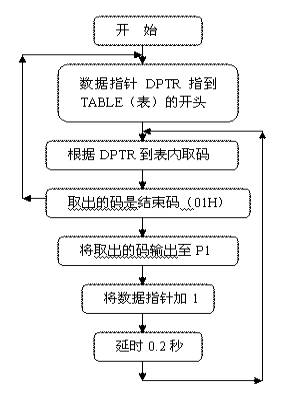
Therefore, as long as the control code is built into a table and MOVC A, @A + DPTR is used to perform code retrieval operations, some complex control actions can be easily processed. The table retrieval process is shown in the figure below:
5.
Program flow chart
Figure 4.5.2
6. Assembly source program
ORG 0
START: MOV DPTR,#TABLE
LOOP: CLR A
MOVC A,@A+DPTR
CJNE A,#01H,LOOP1
JMP START
LOOP1: MOV P1,A
MOV R3,#20
LCALL DELAY
INC DPTR
JMP LOOP
DELAY : MOV R4,#20
D1: MOV R5,#248
DJNZ R5,$
DJNZ R4,D1
DJNZ R3,DELAY
RET
TABLE: DB 0FEH,0FDH,0FBH,0F7H
DB 0EFH,0DFH,0BFH,07FH
DB 0FEH,0FDH,0FBH ,0F7H
DB 0EFH,0DFH,0BFH,07FH
DB 07FH,0BFH,0DFH,0EFH
DB 0F7H,0FBH,0FDH,0FEH
DB 07FH,0BFH,0DFH,0EFH
DB 0F7H,0FBH,0FDH,0FEH
DB 00H, 0FFH,00H, 0FFH
DB 01H
END
7. C language source program
#include
unsigned char code table[]={0xfe,0xfd,0xfb,0xf7,
0xef,0xdf,0xbf,0x7f,
0xfe,0xfd,0xfb,0xf7,
0xef,0xdf,0xbf,0x7f
unsigned char i ; void
delay (void) { unsigned char m,n,s; for(m=20;m>0;m--) for(n=20;n>0;n--) for(s=248;s>0;s--); } void main(void) { while(1) { if(table !=0x01) { P1=table ; i++; delay(); } else { i=0; } } }
Reference address:5. Advertising lights (using meter reading method)
: Use the table to make the port P1 change a single light: move left 2 times, move right 2 times, and flash 2 times (delay time 0.2 seconds).
2. Circuit diagram

Use an 8-core cable to connect P1.0-P1.7 in the "single-chip system" area to the L1-L8 ports in the "eight-way LED indicator module" area. The requirements are: P1.0 corresponds to L1, P1.1 corresponds to L2, ..., P1.7 corresponds to L8.
4. Program design content
When using a table for programming, the following instructions must be used to complete
(1).
(2).
Therefore, as long as the control code is built into a table and MOVC A, @A + DPTR is used to perform code retrieval operations, some complex control actions can be easily processed. The table retrieval process is shown in the figure below:
5.

ORG 0
START: MOV DPTR,#TABLE
LOOP: CLR A
MOVC A,@A+DPTR
CJNE A,#01H,LOOP1
JMP START
LOOP1: MOV P1,A
MOV R3,#20
LCALL DELAY
INC DPTR
JMP LOOP
DELAY : MOV R4,#20
D1: MOV R5,#248
DJNZ R5,$
DJNZ R4,D1
DJNZ R3,DELAY
RET
TABLE: DB 0FEH,0FDH,0FBH,0F7H
DB 0EFH,0DFH,0BFH,07FH
DB 0FEH,0FDH,0FBH ,0F7H
DB 0EFH,0DFH,0BFH,07FH
DB 07FH,0BFH,0DFH,0EFH
DB 0F7H,0FBH,0FDH,0FEH
DB 07FH,0BFH,0DFH,0EFH
DB 0F7H,0FBH,0FDH,0FEH
DB 00H, 0FFH,00H, 0FFH
DB 01H
END
7. C language source program
#include
unsigned char code table[]={0xfe,0xfd,0xfb,0xf7,
0xef,0xdf,0xbf,0x7f,
0xfe,0xfd,0xfb,0xf7,
0xef,0xdf,0xbf,0x7f
unsigned char i ; void
delay (void) { unsigned char m,n,s; for(m=20;m>0;m--) for(n=20;n>0;n--) for(s=248;s>0;s--); } void main(void) { while(1) { if(table !=0x01) { P1=table ; i++; delay(); } else { i=0; } } }
Previous article:6. Alarm generator
Next article:3. Multi-way switch status indication
- Popular Resources
- Popular amplifiers
Recommended Content
Latest Microcontroller Articles
- Learn ARM development(16)
- Learn ARM development(17)
- Learn ARM development(18)
- Embedded system debugging simulation tool
- A small question that has been bothering me recently has finally been solved~~
- Learn ARM development (1)
- Learn ARM development (2)
- Learn ARM development (4)
- Learn ARM development (6)
He Limin Column
Microcontroller and Embedded Systems Bible
 Professor at Beihang University, dedicated to promoting microcontrollers and embedded systems for over 20 years.
MoreSelected Circuit Diagrams
MorePopular Articles
- LED chemical incompatibility test to see which chemicals LEDs can be used with
- Application of ARM9 hardware coprocessor on WinCE embedded motherboard
- What are the key points for selecting rotor flowmeter?
- LM317 high power charger circuit
- A brief analysis of Embest's application and development of embedded medical devices
- Single-phase RC protection circuit
- stm32 PVD programmable voltage monitor
- Introduction and measurement of edge trigger and level trigger of 51 single chip microcomputer
- Improved design of Linux system software shell protection technology
- What to do if the ABB robot protection device stops
MoreDaily News
- Analysis of the application of several common contact parts in high-voltage connectors of new energy vehicles
- Wiring harness durability test and contact voltage drop test method
- From probes to power supplies, Tektronix is leading the way in comprehensive innovation in power electronics testing
- From probes to power supplies, Tektronix is leading the way in comprehensive innovation in power electronics testing
- Sn-doped CuO nanostructure-based ethanol gas sensor for real-time drunk driving detection in vehicles
- Design considerations for automotive battery wiring harness
- Do you know all the various motors commonly used in automotive electronics?
- What are the functions of the Internet of Vehicles? What are the uses and benefits of the Internet of Vehicles?
- Power Inverter - A critical safety system for electric vehicles
- Analysis of the information security mechanism of AUTOSAR, the automotive embedded software framework
Guess you like
- ADI Think Tank Secrets New Release丨High Speed Circuit Design Guide is now available for download
- 【LAUNCHXL-CC1350-4】- 1: Install CCS on Ubuntu 20.04
- Review summary: RTT & Renesas high-performance CPK-RA6M4 development board
- Two methods of chip unpacking
- MSP430FR25x2 Capacitive Touch Sensing Mixed-Signal Microcontrollers
- Analog circuit basics: from system level to circuit level
- HyperLynx High-Speed Circuit Design and Simulation (II) Reflection due to unequal transmission line impedance and power supply impedance
- OS_STM32F103 V2.0 version project source code.
- I feel that the STM32H750XB is useless.
- Urgent!!! How to get download points?

 EL5462ISZ


 京公网安备 11010802033920号