1. Experimental task:
Use P1.0 to output 1KHz and 500Hz audio signals to drive the speaker as an alarm signal. The 1KHz signal is required to sound for 100ms and the 500Hz signal is required to sound for 200ms, alternately. P1.7 is connected to a switch for control. When the switch is closed, the alarm signal sounds, and when the switch is opened, the alarm signal stops. Write a program.
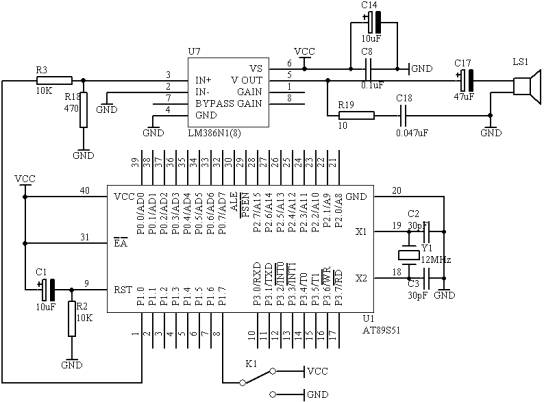
2.Circuit diagram

Figure 4.6.1
3. Hardware connection on the system board
(1. Connect the P1.0 port in the "MCU system" area to the SPK IN port in the "Audio amplifier module" area with a wire;
(2. Connect an 8-ohm or 16-ohm speaker to the SPK OUT port in the "
Audio amplifier module" area; (3. Connect the P1.7/RD port in the "MCU system" area to the K1 port in the "Four-way toggle switch" area with a wire;
4.Program design content
(1. Signal generation method
500Hz signal period is 2ms, signal level reverses once every 1ms, 1KHz signal period is 1ms, signal level reverses once every 500us;
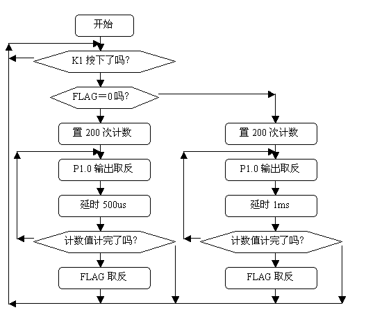
5.Program flowchart
start
Is K1 pressed?
Is FLAG=0?
Set to 200 counts
P1.0 output inversion
Delay 500us
Is the count complete?
FLAG inversion
Set to 200 counts
P1.0 output inversion
Delay 1ms
Is the count complete?
FLAG inversion


Figure 4.6.2
6. Assembly source program
FLAG BIT 00H
ORG 00H
START: JB P1.7,START
JNB FLAG,NEXT
MOV R2,#200
DV: CPL P1.0
LCALL DELY500
LCALL DELY500
DJNZ R2,DV
CPL FLAG
NEXT: MOV R2,#200
DV1: CPL P1.0
LCALL DELY500
DJNZ R2,DV1
CPL FLAG
SJMP START
DELY500: MOV R7,#250
LOOP: NOP
DJNZ R7,LOOP
RET
END
7.C language source program
#include
#include
bit flag;
unsigned char count;
void dely500(void)
{
unsigned char i;
for(i=250;i>0;i--)
{
_nop_();
}
}
void main(void)
{
while(1)
{
if(P1_7==0)
{
for(count=200;count>0;count--)
{
P1_0=~P1_0;
dely500();
}
for(count=200;count>0;count--)
{
P1_0=~P1_0;
dely500();
dely500();
}
}
}
}
Reference address:6. Alarm generator
Use P1.0 to output 1KHz and 500Hz audio signals to drive the speaker as an alarm signal. The 1KHz signal is required to sound for 100ms and the 500Hz signal is required to sound for 200ms, alternately. P1.7 is connected to a switch for control. When the switch is closed, the alarm signal sounds, and when the switch is opened, the alarm signal stops. Write a program.
2.

(1. Connect the P1.0 port in the "MCU system" area to the SPK IN port in the "Audio amplifier module" area with a wire;
(2. Connect an 8-ohm or 16-ohm speaker to the SPK OUT port in the "
Audio amplifier module" area; (3. Connect the P1.7/RD port in the "MCU system" area to the K1 port in the "Four-way toggle switch" area with a wire;
4.
(1. Signal generation method
500Hz signal period is 2ms, signal level reverses once every 1ms, 1KHz signal period is 1ms, signal level reverses once every 500us;
5.
Set to 200 counts
Set to 200 counts


FLAG BIT 00H
ORG 00H
START: JB P1.7,START
JNB FLAG,NEXT
MOV R2,#200
DV: CPL P1.0
LCALL DELY500
LCALL DELY500
DJNZ R2,DV
CPL FLAG
NEXT: MOV R2,#200
DV1: CPL P1.0
LCALL DELY500
DJNZ R2,DV1
CPL FLAG
SJMP START
DELY500: MOV R7,#250
LOOP: NOP
DJNZ R7,LOOP
RET
END
7.
#include
#include
bit flag;
unsigned char count;
void dely500(void)
{
unsigned char i;
for(i=250;i>0;i--)
{
_nop_();
}
}
void main(void)
{
while(1)
{
if(P1_7==0)
{
for(count=200;count>0;count--)
{
P1_0=~P1_0;
dely500();
}
for(count=200;count>0;count--)
{
P1_0=~P1_0;
dely500();
dely500();
}
}
}
}
Previous article:7. I/O parallel port directly drives LED display
Next article:5. Advertising lights (using meter reading method)
- Popular Resources
- Popular amplifiers
Recommended Content
Latest Microcontroller Articles
He Limin Column
Microcontroller and Embedded Systems Bible
 Professor at Beihang University, dedicated to promoting microcontrollers and embedded systems for over 20 years.
MoreSelected Circuit Diagrams
MorePopular Articles
- LED chemical incompatibility test to see which chemicals LEDs can be used with
- Application of ARM9 hardware coprocessor on WinCE embedded motherboard
- What are the key points for selecting rotor flowmeter?
- LM317 high power charger circuit
- A brief analysis of Embest's application and development of embedded medical devices
- Single-phase RC protection circuit
- stm32 PVD programmable voltage monitor
- Introduction and measurement of edge trigger and level trigger of 51 single chip microcomputer
- Improved design of Linux system software shell protection technology
- What to do if the ABB robot protection device stops
MoreDaily News
- P22-009_Butterfly E3106 Cord Board Solution
- Keysight Technologies Helps Samsung Electronics Successfully Validate FiRa® 2.0 Safe Distance Measurement Test Case
- Innovation is not limited to Meizhi, Welling will appear at the 2024 China Home Appliance Technology Conference
- Innovation is not limited to Meizhi, Welling will appear at the 2024 China Home Appliance Technology Conference
- Huawei's Strategic Department Director Gai Gang: The cumulative installed base of open source Euler operating system exceeds 10 million sets
- Download from the Internet--ARM Getting Started Notes
- Learn ARM development(22)
- Learn ARM development(21)
- Learn ARM development(20)
- Learn ARM development(19)
Guess you like
- Pingtouge RISC-V development board--STEP2--CDK environment construction learning, let the LED light start flashing
- Getting Started with MSP430F5529
- HPM6750 Evaluation of Pioneer Semiconductor Step 4 (FreeRTOS+TinyUSB+LVGL) Comprehensive Example
- Understanding the configuration of C2000 series CMD files
- MicroPython Hands-on (01)——After the Spring Festival, I bought a K210 chip AI development board
- FP8102 1A single-cell lithium-ion linear charging IC
- Design of Passive Acoustic Target Detection Platform Based on Single Chip Microcomputer and DSP
- 6. "Wanli" Raspberry Pi car - wiringPi learning (PWM and external interrupt simulation timer)
- Design of low power portable electrocardiograph based on MSP430
- EEWORLD University Hall----Live Replay: Application of TI mmWave Radar Sensors in Smart Home and Smart Security

 KA258D


 京公网安备 11010802033920号