TFT-LCD is a thin film transistor liquid crystal display. Its full English name is: Thin Film Transistor-Liquid Crystal Display. TFT-LCD is different from the simple matrix of passive TN-LCD and STN-LCD. It has a thin film transistor (TFT) on each pixel of the liquid crystal display screen, which can effectively overcome the crosstalk when it is not selected, so that the static characteristics of the display liquid crystal screen are independent of the number of scanning lines, thus greatly improving the image quality. TFT-LCD is also called a true color liquid crystal display.
TFT liquid crystal principle:
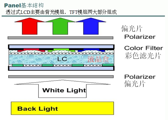
*Backlight module: provides light source
*Upper and lower polarizers, TFT Glass Substrate, liquid crystal: forms polarized light and controls whether the light passes through
*Color filter: provides the source of TFT LCD R/G/B (three primary colors)
*ITO transparent conductive layer: provides a transparent conductive path
*Photo Spacer: provides a fixed height for the color filter and TFT Glass Substrate, as a space for injecting liquid crystal, and as a support for the upper and lower layers of Glass
Liquid crystal characteristics:
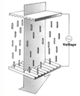
The liquid crystal used in TFT-LCD is TN (Twist Nematic) type liquid crystal, and the molecules are elliptical. TN type liquid crystal is generally connected in series along the long axis direction, and the long axes are arranged in parallel to each other; when it contacts the groove surface, the liquid crystal molecules will be
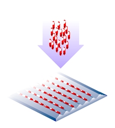
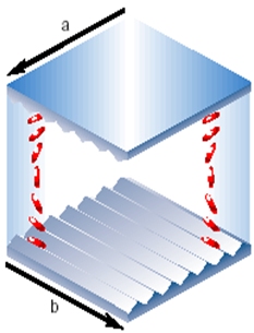
arranged along the direction of the groove. When the liquid crystal is contained in the middle of two groove surfaces, and the directions of the grooves are perpendicular to each other, the arrangement of the liquid crystal molecules is:
a) Upper surface molecules: along direction a;
b) Lower surface molecules: along direction b;
c) Molecules between the upper and lower surfaces: produce a rotation effect.
Therefore, the liquid crystal molecules produce a 90° rotation between the two groove surfaces.
When linear polarized light enters the upper groove surface, this light also rotates with the rotation of the liquid crystal molecules.
When the linear polarized light exits the lower groove surface, this light has already produced a 90-degree rotation .
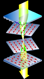
When a voltage is applied between the upper and lower surfaces, the liquid crystal molecules will be arranged along the direction of the electric field. At this time, the incident light will no longer rotate, so the light will exit the lower surface in a straight line.
Polarizer characteristics:
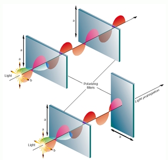
filter non-polarized light (normal light) into polarized light.
When non-polarized light passes through the polarizer in the direction of a, the light is filtered into linear polarized light parallel to the direction of a
. Top: The polarization direction is the same, the linear polarized light continues to move forward, and the light passes through the second polarizer.
Bottom: The polarization direction is different, and the light is completely blocked when passing through the second polarizer. Polarized light
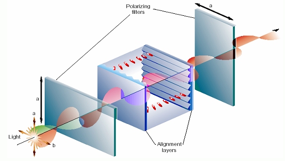
passes through the liquid crystal molecules, the polarization direction rotates, and the light can pass through the polarizer.
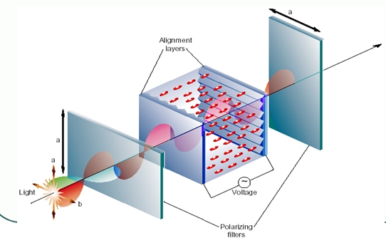
When the liquid crystal molecules are arranged in the direction shown in the figure, the polarization direction of the light will no longer rotate, and ultimately cannot pass through the polarizer.
There are polarizers with perpendicular polarization directions on the top and bottom of the TFT. After the light emitted by the backlight panel is scattered by the backlight module, it first passes through the lower polarizer to form polarized light
and then passes through the liquid crystal molecules. The polarization direction after passing through the liquid crystal molecules is determined by the rotation angle of the liquid crystal molecules.
After passing through the color filter, red, green, and blue light is generated, and finally passes through the upper polarizer. The final output light intensity is determined by the angle between the polarization direction of the polarized light and the polarizer polarization direction to form different colors.
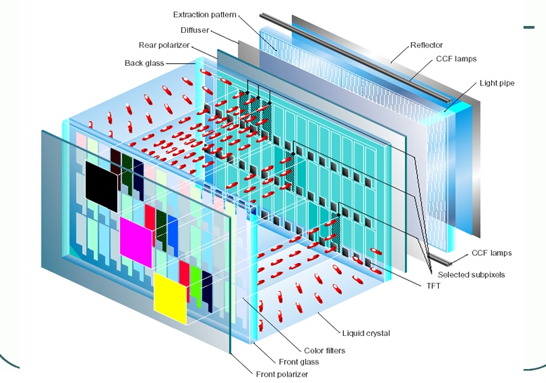
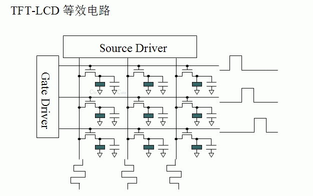
The intensity of light emission is controlled by MOS tubes to control the deflection angle of liquid crystal, thereby controlling the intensity of light exit to achieve the purpose of controlling color.
Assuming a 240*320 resolution liquid crystal, since the basic colors are 3 primary colors, there are a total of 240*320*3 MOS tubes.
"Pixel" is composed of the letters of the two words Picture and Element. It is a unit used to calculate digital images. Just like photographic photos, digital images also have continuous shades. If we magnify the image several times, we will find that these continuous tones are actually composed of many small squares of similar colors. These small squares are the smallest unit of the image, "Pixel". This smallest graphic unit can usually display a single dyed point on the screen. The higher the pixel, the richer the color palette it has, and the more it can express the realism of the color.
How is the color displayed by each point determined?
Since I use a 2.8-inch TFT LCD with a resolution of 240*320 (pixels) and a 16-bit true color display (close to natural colors),
the module uses the DST2001PH TFTLCD of Xianshang Optoelectronics. The controller of DST2001PH is ILI9320 (may be others), and a 16-bit 80 parallel port is used.
The relationship between the driver chip memory GRAM and color:

Since it is 16-bit data, the lowest 5 bits represent blue, the middle 6 bits represent green, and the highest 5 bits represent red. The larger the value, the darker the color.
It means writing different data into the video memory to produce different colors.
Common color determination:
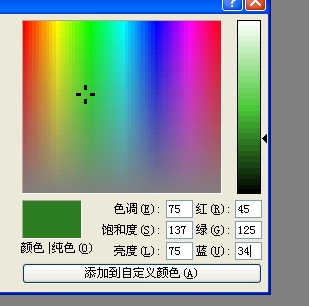
Use the 3 primary colors in the drawing tool to determine the required video memory data.
I use the ALIENTEK MiniSTM32 development board to equip myself with a 2.8-inch LCD.
The hardware interface of the LCD driver chip:
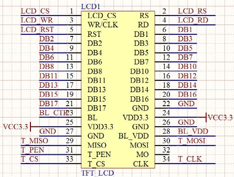
uses a 16-bit data line (if it is too slow, it will have no effect when using color). The 80 parallel port of this module has the following signal lines:
CS: TFTLCD chip select signal.
WR: Write data to TFTLCD.
RD: Read data from TFTLCD.
D[15:0]: 16-bit bidirectional data line.
RST: Hard reset TFTLCD.
RS: Command/data flag (0, read/write command; 1, read/write data).
Common register instructions for ILI9320:

R0, this command has two functions. If it is written, the lowest bit is OSC, which is used to turn on or off the oscillator. If it is read, the controller model is returned. The biggest function of this command is that the controller model can be obtained by reading it. After knowing the controller model, our code can perform different initializations for different controller models. Because the initialization of the 93xx series is actually similar, we can use one code to be compatible with several controllers.
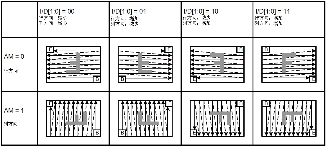
R3, entry mode command. We focus on the three bits I/D0, I/D1, and AM, because these three bits control the display direction of the screen.
//------------------------------------------------------------------------------------------------------------------------------------------
AM: Control the update direction of GRAM. When AM=0, the address is updated in the row direction. When AM=1, the address is updated in the column direction.
I/D[1:0]: After a data is updated, the address counter is automatically increased/decreased by 1 according to the settings of these two bits.
/--------------------------------------------------------------------------------------------------------------------------------------------
R7: Display control command. The CL bit of this command is used to control whether it is 8-bit color or 260,000 colors. When it is 0, it is 260,000 colors, and when it is 1, it is 8-bit color. The three bits D1, D0, and BASEE are used to control whether the display is on or off. When all are set to 1, the display is turned on, and all 0 is turned off. We usually turn the display on or off by setting this command to reduce power consumption.
R32, R33: Set the row address and column address of GRAM. R32 is used to set the column address (X coordinate, 0~239), and R33 is used to set the row address (Y coordinate, 0~319). When we want to write a color to a specified point, we first set it to the point through these two commands, and then write the color value.
R34: Write data to GRAM command. After this command is written, the address counter will automatically increase and decrease. This command is the only single operation command in the group of commands we are going to introduce. You only need to write the value. For the others, you need to write the command number first and then write the operand.
R80~R83: Row and column GRAM address location setting. These commands are used to set the size of your display area. The size of our entire screen is 240*320, but sometimes we only need to write data in a part of it. If we use the method of writing coordinates first and then writing data, the speed will be greatly reduced. At this time, we can use these commands to open up an area in it, and then keep throwing data. The address counter will automatically increase/decrease according to the setting of R3, so there is no need to write addresses frequently, which greatly improves the refresh speed.
//--------------------------------------------------------------------------------------------------------
Next, let's see how to drive the ALIENTEK TFTLCD module. The relevant setting steps required for TFTLCD display are as follows:
1) Set the IO connected to the STM32 and TFTLCD module.
In this step, first set the IO port connected to the TFTLCD module as output. The specific IO ports to be used need to be determined according to the connection circuit and the settings of the TFTLCD module.
2) Initialize the TFTLCD module.
In fact, this is similar to the initialization process of the OLED module above. Start the display of the TFTLCD by writing a series of settings to the TFTLCD. Prepare for the subsequent display of characters and numbers.
3) Use functions to display characters and numbers on the TFTLCD module.
The IO port correspondence of the MiniSTM32 development board is as follows:
LCD_LED corresponds to PC10;
LCD_CS corresponds to PC9;
LCD _RS corresponds to PC8;
LCD _WR corresponds to PC7;
LCD _RD corresponds to PC6;
LCD _D[17:1] corresponds to PB[15:0];
Keywords:STM32
Reference address:STM32 TFT-LCD liquid crystal
TFT liquid crystal principle:

*Backlight module: provides light source
*Upper and lower polarizers, TFT Glass Substrate, liquid crystal: forms polarized light and controls whether the light passes through
*Color filter: provides the source of TFT LCD R/G/B (three primary colors)
*ITO transparent conductive layer: provides a transparent conductive path
*Photo Spacer: provides a fixed height for the color filter and TFT Glass Substrate, as a space for injecting liquid crystal, and as a support for the upper and lower layers of Glass
Liquid crystal characteristics:
The liquid crystal used in TFT-LCD is TN (Twist Nematic) type liquid crystal, and the molecules are elliptical. TN type liquid crystal is generally connected in series along the long axis direction, and the long axes are arranged in parallel to each other; when it contacts the groove surface, the liquid crystal molecules will be

arranged along the direction of the groove. When the liquid crystal is contained in the middle of two groove surfaces, and the directions of the grooves are perpendicular to each other, the arrangement of the liquid crystal molecules is:
a) Upper surface molecules: along direction a;
b) Lower surface molecules: along direction b;
c) Molecules between the upper and lower surfaces: produce a rotation effect.
Therefore, the liquid crystal molecules produce a 90° rotation between the two groove surfaces.

When linear polarized light enters the upper groove surface, this light also rotates with the rotation of the liquid crystal molecules.
When the linear polarized light exits the lower groove surface, this light has already produced a 90-degree rotation .

When a voltage is applied between the upper and lower surfaces, the liquid crystal molecules will be arranged along the direction of the electric field. At this time, the incident light will no longer rotate, so the light will exit the lower surface in a straight line.

Polarizer characteristics:
filter non-polarized light (normal light) into polarized light.
When non-polarized light passes through the polarizer in the direction of a, the light is filtered into linear polarized light parallel to the direction of a
. Top: The polarization direction is the same, the linear polarized light continues to move forward, and the light passes through the second polarizer.
Bottom: The polarization direction is different, and the light is completely blocked when passing through the second polarizer. Polarized light

passes through the liquid crystal molecules, the polarization direction rotates, and the light can pass through the polarizer.

When the liquid crystal molecules are arranged in the direction shown in the figure, the polarization direction of the light will no longer rotate, and ultimately cannot pass through the polarizer.

There are polarizers with perpendicular polarization directions on the top and bottom of the TFT. After the light emitted by the backlight panel is scattered by the backlight module, it first passes through the lower polarizer to form polarized light
and then passes through the liquid crystal molecules. The polarization direction after passing through the liquid crystal molecules is determined by the rotation angle of the liquid crystal molecules.
After passing through the color filter, red, green, and blue light is generated, and finally passes through the upper polarizer. The final output light intensity is determined by the angle between the polarization direction of the polarized light and the polarizer polarization direction to form different colors.


The intensity of light emission is controlled by MOS tubes to control the deflection angle of liquid crystal, thereby controlling the intensity of light exit to achieve the purpose of controlling color.
Assuming a 240*320 resolution liquid crystal, since the basic colors are 3 primary colors, there are a total of 240*320*3 MOS tubes.
"Pixel" is composed of the letters of the two words Picture and Element. It is a unit used to calculate digital images. Just like photographic photos, digital images also have continuous shades. If we magnify the image several times, we will find that these continuous tones are actually composed of many small squares of similar colors. These small squares are the smallest unit of the image, "Pixel". This smallest graphic unit can usually display a single dyed point on the screen. The higher the pixel, the richer the color palette it has, and the more it can express the realism of the color.
How is the color displayed by each point determined?
Since I use a 2.8-inch TFT LCD with a resolution of 240*320 (pixels) and a 16-bit true color display (close to natural colors),
the module uses the DST2001PH TFTLCD of Xianshang Optoelectronics. The controller of DST2001PH is ILI9320 (may be others), and a 16-bit 80 parallel port is used.
The relationship between the driver chip memory GRAM and color:

Since it is 16-bit data, the lowest 5 bits represent blue, the middle 6 bits represent green, and the highest 5 bits represent red. The larger the value, the darker the color.
It means writing different data into the video memory to produce different colors.
Common color determination:

Use the 3 primary colors in the drawing tool to determine the required video memory data.
I use the ALIENTEK MiniSTM32 development board to equip myself with a 2.8-inch LCD.
The hardware interface of the LCD driver chip:

uses a 16-bit data line (if it is too slow, it will have no effect when using color). The 80 parallel port of this module has the following signal lines:
CS: TFTLCD chip select signal.
WR: Write data to TFTLCD.
RD: Read data from TFTLCD.
D[15:0]: 16-bit bidirectional data line.
RST: Hard reset TFTLCD.
RS: Command/data flag (0, read/write command; 1, read/write data).
Common register instructions for ILI9320:

R0, this command has two functions. If it is written, the lowest bit is OSC, which is used to turn on or off the oscillator. If it is read, the controller model is returned. The biggest function of this command is that the controller model can be obtained by reading it. After knowing the controller model, our code can perform different initializations for different controller models. Because the initialization of the 93xx series is actually similar, we can use one code to be compatible with several controllers.
R3, entry mode command. We focus on the three bits I/D0, I/D1, and AM, because these three bits control the display direction of the screen.
//------------------------------------------------------------------------------------------------------------------------------------------
AM: Control the update direction of GRAM. When AM=0, the address is updated in the row direction. When AM=1, the address is updated in the column direction.
I/D[1:0]: After a data is updated, the address counter is automatically increased/decreased by 1 according to the settings of these two bits.
/--------------------------------------------------------------------------------------------------------------------------------------------

R7: Display control command. The CL bit of this command is used to control whether it is 8-bit color or 260,000 colors. When it is 0, it is 260,000 colors, and when it is 1, it is 8-bit color. The three bits D1, D0, and BASEE are used to control whether the display is on or off. When all are set to 1, the display is turned on, and all 0 is turned off. We usually turn the display on or off by setting this command to reduce power consumption.
R32, R33: Set the row address and column address of GRAM. R32 is used to set the column address (X coordinate, 0~239), and R33 is used to set the row address (Y coordinate, 0~319). When we want to write a color to a specified point, we first set it to the point through these two commands, and then write the color value.
R34: Write data to GRAM command. After this command is written, the address counter will automatically increase and decrease. This command is the only single operation command in the group of commands we are going to introduce. You only need to write the value. For the others, you need to write the command number first and then write the operand.
R80~R83: Row and column GRAM address location setting. These commands are used to set the size of your display area. The size of our entire screen is 240*320, but sometimes we only need to write data in a part of it. If we use the method of writing coordinates first and then writing data, the speed will be greatly reduced. At this time, we can use these commands to open up an area in it, and then keep throwing data. The address counter will automatically increase/decrease according to the setting of R3, so there is no need to write addresses frequently, which greatly improves the refresh speed.
//--------------------------------------------------------------------------------------------------------
Next, let's see how to drive the ALIENTEK TFTLCD module. The relevant setting steps required for TFTLCD display are as follows:
1) Set the IO connected to the STM32 and TFTLCD module.
In this step, first set the IO port connected to the TFTLCD module as output. The specific IO ports to be used need to be determined according to the connection circuit and the settings of the TFTLCD module.
2) Initialize the TFTLCD module.
In fact, this is similar to the initialization process of the OLED module above. Start the display of the TFTLCD by writing a series of settings to the TFTLCD. Prepare for the subsequent display of characters and numbers.
3) Use functions to display characters and numbers on the TFTLCD module.
The IO port correspondence of the MiniSTM32 development board is as follows:
LCD_LED corresponds to PC10;
LCD_CS corresponds to PC9;
LCD _RS corresponds to PC8;
LCD _WR corresponds to PC7;
LCD _RD corresponds to PC6;
LCD _D[17:1] corresponds to PB[15:0];
Introduction to basic GUI interface functions (I)
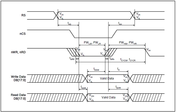
80 parallel port timing diagram:
(I):
//------Write data function--------- Here we use the macro definition method to increase the speed (due to the frequent writing and reading of display images):
#define LCD_WR_DATA(data){\
LCD_RS_SET;\ //Select data
LCD_CS_CLR;\ //Select chip
DATAOUT(data);\ //Put the data into the port
LCD_WR_CLR;\ //WR writes data to a rising edge (writes data)
LCD_WR_SET;\
LCD_CS_SET;\ //CS rising edge writes data completed
}
The '\' in the above function is an escape character in the C language, used to connect the context, because the macro definition can only be a string, and when your string is too long (more than one line), you need to wrap, at this time you must use a backslash to connect the context. The '\' here plays this role
(II):
Because this function is not used very frequently, macro definition is not used
//----Send instruction function to register------
void LCD_WR_REG(u8 data)
{
LCD_RS_CLR; //Select instruction
LCD_CS_CLR; //Select chip
DATAOUT(data); //Put instruction on the port
LCD_WR_CLR; //WR writes data to a rising edge (write data)
LCD_WR_SET;
LCD_CS_SET; //CS is up to complete the operation
}
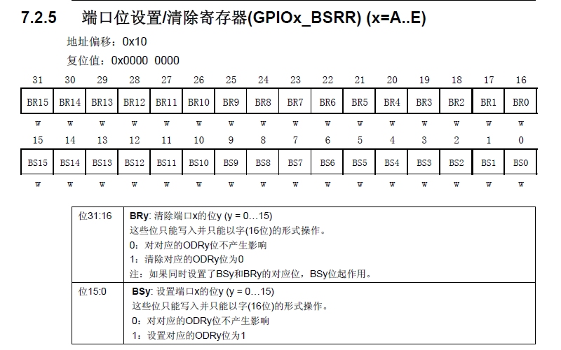
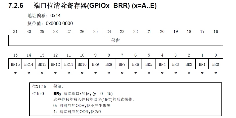
(III): Set fast IO
by the following 2 registers
//-------Read register value function---------
u16 LCD_ReadReg(u8 LCD_Reg)
{
u16 t;
LCD_WR_REG(LCD_Reg); //Write the register number to be read
GPIOB->CRL=0x88888888; //Set port PORTB to input mode
GPIOB->CRH=0x88888888;
GPIOB->ODR=0xffff; //Port pull-up to prepare input
#ifdef LCD_FAST_IO //Judge whether the fast IO port has been macro-defined
LCD_RS_SET; //Use the fast IO port (Example: #define LCD_CS_SET GPIOC->BSRR=1<<9 //Chip select port PC9)
LCD_CS_CLR;
LCD_RD_CLR;
LCD_RD_SET; //RD pin generates a rising edge
t=DATAIN;
LCD_CS_SET;
#endif
GPIOB->CRL=0x33333333; //Restore output status
GPIOB->CRH=0x33333333;
GPIOB->ODR=0xffff;
return t;
}

(I):
//------Write data function--------- Here we use the macro definition method to increase the speed (due to the frequent writing and reading of display images):
#define LCD_WR_DATA(data){\
LCD_RS_SET;\ //Select data
LCD_CS_CLR;\ //Select chip
DATAOUT(data);\ //Put the data into the port
LCD_WR_CLR;\ //WR writes data to a rising edge (writes data)
LCD_WR_SET;\
LCD_CS_SET;\ //CS rising edge writes data completed
}
The '\' in the above function is an escape character in the C language, used to connect the context, because the macro definition can only be a string, and when your string is too long (more than one line), you need to wrap, at this time you must use a backslash to connect the context. The '\' here plays this role
(II):
Because this function is not used very frequently, macro definition is not used
//----Send instruction function to register------
void LCD_WR_REG(u8 data)
{
LCD_RS_CLR; //Select instruction
LCD_CS_CLR; //Select chip
DATAOUT(data); //Put instruction on the port
LCD_WR_CLR; //WR writes data to a rising edge (write data)
LCD_WR_SET;
LCD_CS_SET; //CS is up to complete the operation
}
(III): Set fast IO
by the following 2 registers


//-------Read register value function---------
u16 LCD_ReadReg(u8 LCD_Reg)
{
u16 t;
LCD_WR_REG(LCD_Reg); //Write the register number to be read
GPIOB->CRL=0x88888888; //Set port PORTB to input mode
GPIOB->CRH=0x88888888;
GPIOB->ODR=0xffff; //Port pull-up to prepare input
#ifdef LCD_FAST_IO //Judge whether the fast IO port has been macro-defined
LCD_RS_SET; //Use the fast IO port (Example: #define LCD_CS_SET GPIOC->BSRR=1<<9 //Chip select port PC9)
LCD_CS_CLR;
LCD_RD_CLR;
LCD_RD_SET; //RD pin generates a rising edge
t=DATAIN;
LCD_CS_SET;
#endif
GPIOB->CRL=0x33333333; //Restore output status
GPIOB->CRH=0x33333333;
GPIOB->ODR=0xffff;
return t;
}
Previous article:STM32 DMA
Next article:STM32 ADC measurement
- Popular Resources
- Popular amplifiers
Recommended Content
Latest Microcontroller Articles
- Learn ARM development(16)
- Learn ARM development(17)
- Learn ARM development(18)
- Embedded system debugging simulation tool
- A small question that has been bothering me recently has finally been solved~~
- Learn ARM development (1)
- Learn ARM development (2)
- Learn ARM development (4)
- Learn ARM development (6)
He Limin Column
Microcontroller and Embedded Systems Bible
 Professor at Beihang University, dedicated to promoting microcontrollers and embedded systems for over 20 years.
MoreSelected Circuit Diagrams
MorePopular Articles
- LED chemical incompatibility test to see which chemicals LEDs can be used with
- Application of ARM9 hardware coprocessor on WinCE embedded motherboard
- What are the key points for selecting rotor flowmeter?
- LM317 high power charger circuit
- A brief analysis of Embest's application and development of embedded medical devices
- Single-phase RC protection circuit
- stm32 PVD programmable voltage monitor
- Introduction and measurement of edge trigger and level trigger of 51 single chip microcomputer
- Improved design of Linux system software shell protection technology
- What to do if the ABB robot protection device stops
MoreDaily News
- Brief Analysis of Automotive Ethernet Test Content and Test Methods
- How haptic technology can enhance driving safety
- Let’s talk about the “Three Musketeers” of radar in autonomous driving
- Why software-defined vehicles transform cars from tools into living spaces
- How Lucid is overtaking Tesla with smaller motors
- Wi-Fi 8 specification is on the way: 2.4/5/6GHz triple-band operation
- Wi-Fi 8 specification is on the way: 2.4/5/6GHz triple-band operation
- Vietnam's chip packaging and testing business is growing, and supply-side fragmentation is splitting the market
- Vietnam's chip packaging and testing business is growing, and supply-side fragmentation is splitting the market
- Three steps to govern hybrid multicloud environments
Guess you like
- Three major programming languages for the development of the Internet of Things
- Since it is so similar to inductors, why can you only use ferrite beads in your circuit?
- Device tree interrupt node
- Can CC2541 support 10 external interrupts?
- PCB failure analysis and some cases
- Xunwei i.MX6ULL Terminator Mfgtools Modify Only Burn Uboot, Kernel, File System
- How to choose the flow capacity
- ADRV9002 Dual Narrow Bandwidth RF Transceiver
- Help, STM32 address data acquisition HardFault_Handler
- CC2640R2 uses the IDE's post-build function to generate a single firmware file

 LM614IWMX/NOPB


 京公网安备 11010802033920号