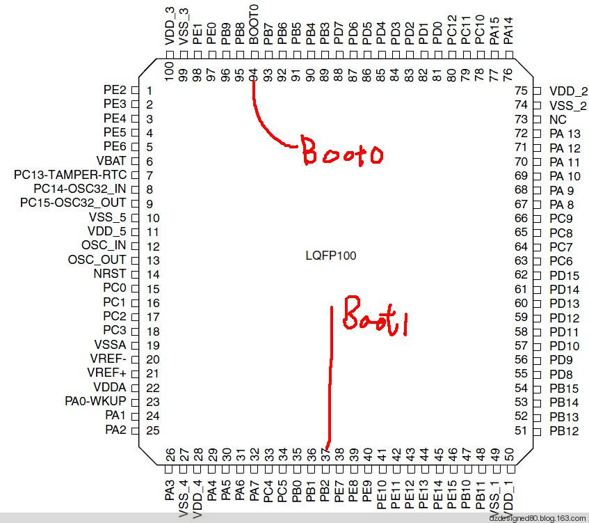
stm32 has a boot pin Boot0 and Boot1, which are used to set the startup position of the code

Keywords:stm32
Reference address:STM32 development board development notes (4) - startup settings
As shown below

Boot0 is located at pin 94, which is a dedicated Boot pin. Boot1 is located at pin 37 and is multiplexed with PB2.
Boot1 Boot0
x 0: boot0 is 0, boot1 is any value, the code starts from the internal program storage area
0 1: Code starts from system storage area (ISP code area)
So by short-circuiting Boot0 to ground, you can change the startup mode by simply changing Boot1.
The current mainboard has MAX232, so use USB to serial port to connect to the mainboard, and cooperate with Flymcu software to read and erase the information, but errors will occur during burning.
FlyMcu (www.mcuisp.com)
It may be due to a problem with the extension cable or a problem with the USB to serial port. It was found that the motherboard and the burning software can only communicate when the baud rate is 115200. I don’t know why. Logically, the ISP program should be adaptive.
Previous article:stm32 interrupt function name table
Next article:stm32 general timer interrupt
- Popular Resources
- Popular amplifiers
Recommended Content
Latest Microcontroller Articles
- Learn ARM development(16)
- Learn ARM development(17)
- Learn ARM development(18)
- Embedded system debugging simulation tool
- A small question that has been bothering me recently has finally been solved~~
- Learn ARM development (1)
- Learn ARM development (2)
- Learn ARM development (4)
- Learn ARM development (6)
He Limin Column
Microcontroller and Embedded Systems Bible
 Professor at Beihang University, dedicated to promoting microcontrollers and embedded systems for over 20 years.
MoreSelected Circuit Diagrams
MorePopular Articles
- LED chemical incompatibility test to see which chemicals LEDs can be used with
- Application of ARM9 hardware coprocessor on WinCE embedded motherboard
- What are the key points for selecting rotor flowmeter?
- LM317 high power charger circuit
- A brief analysis of Embest's application and development of embedded medical devices
- Single-phase RC protection circuit
- stm32 PVD programmable voltage monitor
- Introduction and measurement of edge trigger and level trigger of 51 single chip microcomputer
- Improved design of Linux system software shell protection technology
- What to do if the ABB robot protection device stops
MoreDaily News
- Detailed explanation of intelligent car body perception system
- How to solve the problem that the servo drive is not enabled
- Why does the servo drive not power on?
- What point should I connect to when the servo is turned on?
- How to turn on the internal enable of Panasonic servo drive?
- What is the rigidity setting of Panasonic servo drive?
- How to change the inertia ratio of Panasonic servo drive
- What is the inertia ratio of the servo motor?
- Is it better for the motor to have a large or small moment of inertia?
- What is the difference between low inertia and high inertia of servo motors?
Guess you like
- Thank you for being there +2019
- What are the high frequency characteristics of capacitors?
- Can the EPCS16SI8N chip be read and written directly? Altera configuration chip
- Installation Case | MODBUS to PROFINET Gateway Connects Smart Low Voltage Motors
- [NXP Rapid IoT Review] + Getting Started with NXP Rapid IoT
- What challenges will the 5G era bring to the LED display industry?
- 【Silicon Labs BG22-EK4108A Bluetooth Development Review】+Create a Bluetooth program from scratch
- 【mmWave Studio】Several experiences in problem solving
- Pin constraints are lost in Gaoyun Yunyuan software
- I need a schematic diagram and test program for controlling a four-wire brushless motor with a 51 microcontroller and A4988

 UPC358C


 京公网安备 11010802033920号