This study note is based on the STM32 firmware library V3.0.
Chip model used: STM32F103
Development environment: MDK
*********************************
Lesson 1 Clock Frequency
The internal 8M oscillator of STM32F103 can reach a maximum of 72M after frequency multiplication. Currently, the maximum frequency of TI's M3 series chips can reach 80M.
In the stm32 firmware library 3.0, the selection of clock frequency has been greatly simplified. A lot of operations are done in the background. The function given by the system is SystemInit(). However, some macro definition settings need to be made before calling it. The specific settings are in the system_stm32f10x.c file.
There is a definition like this at the beginning of the file:
//#define SYSCLK_FREQ_HSE HSE_Value
//#define SYSCLK_FREQ_20MHz 20000000
//#define SYSCLK_FREQ_36MHz 36000000
//#define SYSCLK_FREQ_48MHz 48000000
//#define SYSCLK_FREQ_56MHz 56000000
#define SYSCLK_FREQ_72MHz 72000000
The external crystal oscillator recommended by ST is 8M, so the settings of the library functions are all based on the assumption that your hardware has been connected to an 8M crystal oscillator for operation. The above is the recommended CPU frequency selection when the default crystal oscillator is 8M. Here, we choose:
#define SYSCLK_FREQ_72MHz 72000000
, which is the maximum value of 72M that the 103 series can run.
然后这个 C文件继续往下看
#elif defined SYSCLK_FREQ_72MHz
const uint32_t SystemFrequency = SYSCLK_FREQ_72MHz;
const uint32_t SystemFrequency_SysClk = SYSCLK_FREQ_72MHz;
const uint32_t SystemFrequency_AHBClk = SYSCLK_FREQ_72MHz;
const uint32_t SystemFrequency_APB1Clk = (SYSCLK_FREQ_72MHz/2);
const uint32_t SystemFrequency_APB2Clk = SYSCLK_FREQ_72MHz;
These are the speeds of each system when the CPU is defined to run at 72M. They are: hardware frequency, system clock, AHB bus frequency, APB1 bus frequency, APB2 bus frequency. Looking down, we see this:
#elif defined SYSCLK_FREQ_72MHz
static void SetSysClockTo72(void);
This is the function that sets the clock when defining 72M. This function is called by the SetSysClock() function, and
the SetSysClock() function is called by the SystemInit() function. Finally, the SystemInit() function is called by you.
So the process of setting the system clock is:
first, the user program calls the SystemInit() function, which is a library function. Then, in the SystemInit() function, after some necessary register initialization, the SetSysClock() function is called. According to the macro definition of #define SYSCLK_FREQ_72MHz 72000000, the SetSysClock() function knows to call the SetSysClockTo72() function, so there are a lot of troublesome and complicated settings ~!@#$% ^Then, the CPU runs at a speed of 72M. Although it is a bit cumbersome, you only need to know that if the user wants to set the frequency, there are only two things to do in the program:
First: #define SYSCLK_FREQ_72MHz 72000000 in system_stm32f10x.c
Second: call SystemInit()
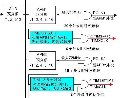
Clock source of timer in STM32
There are up to 8 timers in STM32, of which TIM1 and TIM8 are advanced timers that can generate three pairs of PWM complementary outputs, commonly used to drive three-phase motors, and their clocks are generated by the output of APB2. The other 6 are ordinary timers, and their clocks are generated by the output of APB1.
The following figure is a screenshot of the timer clock section in the clock distribution diagram in the STM32 reference manual:

The following uses the clocks of timers 2 to 7 to illustrate the role of this frequency multiplier: when the pre-scaling factor of APB1 is 1, this frequency multiplier does not work, and the clock frequency of the timer is equal to the frequency of APB1; when the pre-scaling factor of APB1 is other values (that is, the pre-scaling factor is 2, 4, 8 or 16), this frequency multiplier works, and the clock frequency of the timer is equal to twice the frequency of APB1.
Previous article:Why does STM32 have SysTick?
Next article:STM32 Systick programming and application
- Popular Resources
- Popular amplifiers
 Professor at Beihang University, dedicated to promoting microcontrollers and embedded systems for over 20 years.
- LED chemical incompatibility test to see which chemicals LEDs can be used with
- Application of ARM9 hardware coprocessor on WinCE embedded motherboard
- What are the key points for selecting rotor flowmeter?
- LM317 high power charger circuit
- A brief analysis of Embest's application and development of embedded medical devices
- Single-phase RC protection circuit
- stm32 PVD programmable voltage monitor
- Introduction and measurement of edge trigger and level trigger of 51 single chip microcomputer
- Improved design of Linux system software shell protection technology
- What to do if the ABB robot protection device stops
- Huawei's Strategic Department Director Gai Gang: The cumulative installed base of open source Euler operating system exceeds 10 million sets
- Download from the Internet--ARM Getting Started Notes
- Learn ARM development(22)
- Learn ARM development(21)
- Learn ARM development(20)
- Learn ARM development(19)
- Learn ARM development(14)
- Learn ARM development(15)
- Analysis of the application of several common contact parts in high-voltage connectors of new energy vehicles
- Wiring harness durability test and contact voltage drop test method
- Familiar with the basic knowledge of DSP structure
- Millimeter wave sensors enable edge intelligence
- A few key points about interrupts
- Raspberry Pi 4B is here! Want to review it? Get on board now!
- Chapter6 Timer_A
- Do you know the eight important knowledge points of FPGA design?
- Share an ADI one-stop power design tool kit
- TFT LCD interface problem
- [RISC-V MCU CH32V103 Review] + First Use
- [N32L43X Review] 7. Flash read and write cycles

 OP77BIGS-REEL7


 京公网安备 11010802033920号