This article continues the content of the previous article. Let’s do experiment 4: control the active buzzer with a button. The buzzer sounds when the button is pressed and stops when the button is released.
buzzer
Before experiment 4, let's briefly introduce the buzzer. There are two types of buzzers, passive buzzers and active buzzers, which are generally used to sound alarms. Sound is generated by vibration. Everyone has seen a speaker, which has a magnet and a coil inside. When a constantly changing voltage is applied to the coil, it will move in the magnetic field generated by the magnet. Then the diaphragm fixed to the coil will vibrate, and then you can hear the sound. The passive buzzer and the speaker have basically the same effect. Unlike the passive buzzer, the active buzzer has a sound-generating circuit inside, and it will make a sound when a DC current with a suitable voltage is applied. In addition, active buzzers have positive and negative poles. The picture shows a commonly used active buzzer with a working voltage of 5V. The pin on the side marked with a plus sign on the front is the positive pole. If the device is brand new and the pins have not been cut, the positive pin is longer than the negative pole.
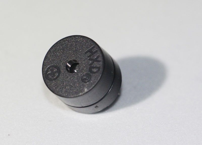
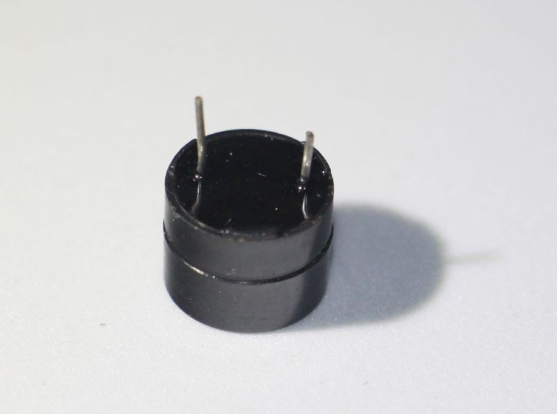
Drive circuit
From the above introduction, we can see that the active buzzer is the same as the LED, it can work as long as it is powered (if there is no special explanation, the buzzer below refers to the active buzzer). But why should it be a separate experiment?
As we said before, the current that can pass through the IO port of the microcontroller is limited. Excessive current may burn out the pins or malfunction. The main difference between a buzzer and an LED is that the buzzer requires much more current than an LED, and the voltage is generally higher.
In order to make the microcontroller drive the buzzer, that is, to control the buzzer, we need to use some special circuits. I don't know if you are familiar with relays. The characteristic of relays is to use small current and low voltage to control large current and high voltage circuits. However, the current required by the control end of a general relay is still too large for a microcontroller, and the price of relays is relatively high. They can control a large current, so it is overkill to use them here. The device we are going to use here is a triode.
Basic introduction of transistor
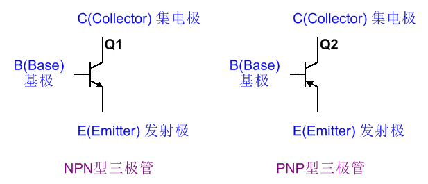
The main function of the transistor is to amplify the current. As the name suggests, the transistor has three pins: emitter, base, and collector, abbreviated as E, B, and C respectively. There are two types, PNP and NPN. The current directions of the two types of transistors are exactly opposite when they are working, and the circuit symbols are also different, as shown in the figure. The arrow on the emitter indicates the direction of the current when working.
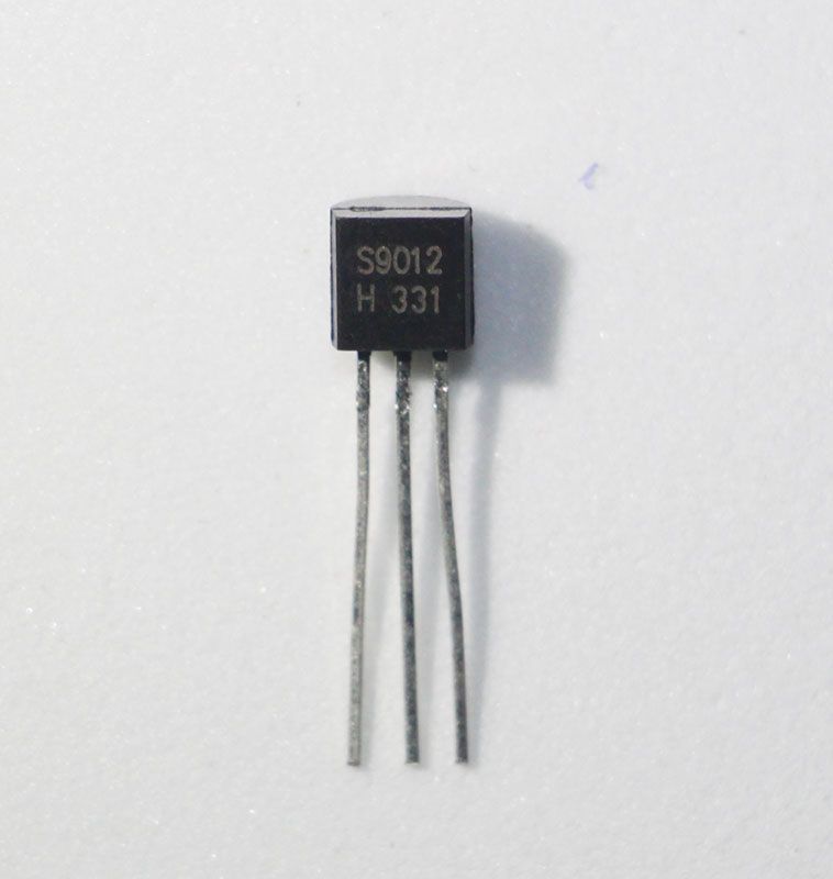
There are many parameters for transistors, and there are many types of actual transistors, and the packages are also various. The picture below is a common TO-92 packaged direct-insertion low-power transistor. Note that this shape is just a package, not dedicated to transistors. There are other devices that use such a package. The specific model depends on the device marked above. For example, S9012 in the picture means it is a 9012 transistor. Place the pins downward as in the picture, with the plane of the semi-cylinder facing you. From left to right, the three pins are E, B, and C.
Transistor used as electronic switch
The transistor has three working states: cut-off region, amplification region, and saturation region. In the amplification region, the electrical signal can be amplified, and the devices we use, such as loudspeakers, can be realized through the transistor. In the single-chip microcomputer, we mainly use the cut-off region and saturation region of the transistor as an electronic switch, and the following circuit diagram is often used.
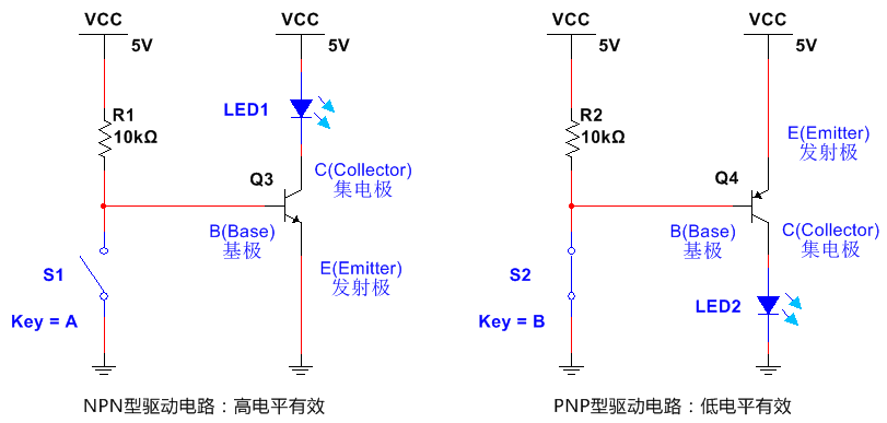
The left and right pictures are the circuit diagrams of NPN and PNP transistors respectively. R1, S1 and R2, S2 are equivalent to the IO port of the microcontroller, and the collector of the transistor is connected to the buzzer. The NPN type circuit controls the buzzer to be effective at high level, that is, when the IO port outputs a high level, the buzzer will sound. The PNP type is the opposite. For the convenience of observation, I connected an LED, which is the same as the buzzer. You can see that the LED is lit in the picture. Note that the pin position of the transistor cannot be reversed, and the load to be driven, that is, the LED in the picture, cannot be reversed.
Commonly used PNP transistors include 9012, 8550, etc., and NPN transistors include 9013, 8050, etc.
The principle of triode and the detailed working condition analysis require a lot of calculations. Interested readers can check the books and materials related to analog circuits. The working mechanism of triode will also be briefly analyzed at the end of the article. Interested students can take a look. If you find it difficult to understand, you don't need to do in-depth research when learning microcontrollers.
Circuit Design
The implementation of the program is similar to lighting up an LED, but it depends on your circuit to determine whether high level or low level is effective. According to the previous transistor circuit, we can use 9012 to implement a buzzer drive circuit, which is effective at low level. The circuit diagram is as follows. Note that the positive and negative poles of the buzzer cannot be connected in reverse.
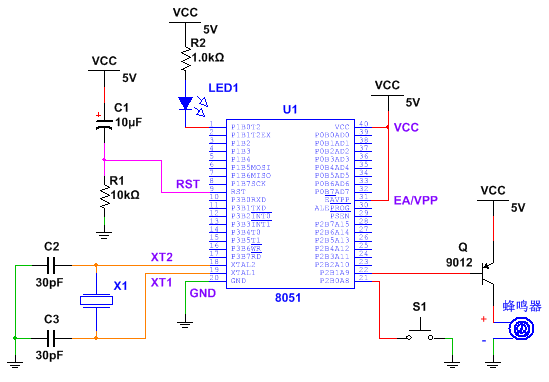
In the figure, the LED connected to P1.0 is still there (of course it can be removed), a push switch is connected to P2.0, and a transistor-driven buzzer is connected to P2.1.
The circuit I built using a breadboard.
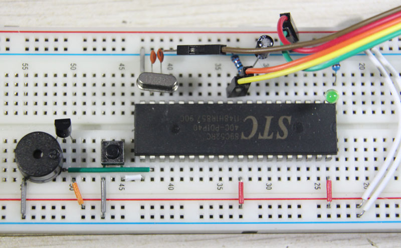
Note: The transistor acts as a switch here, so it is recommended to give priority to using a PNP transistor circuit. Because the function of the transistor is to amplify the current, for the same transistor, if you want to output a larger current, you generally need to input a larger current into the base. When using a PNP circuit, the IO port outputs a low level and is effective, which is a current sink for the microcontroller. At this time, the base can provide a larger current, thereby providing a larger current to drive the buzzer. In my actual test, if I use an NPN transistor 9013, it can drive the LED, but it is not enough to drive the buzzer, unless I connect a pull-up resistor to the IO port.
Program Implementation
First, define the three IO ports of LED, button, and buzzer
sbit LED = P1^0;
sbit KEY = P2^0;
sbit BUZZER = P2^1;
Then set KEY=1 first, and then process it in the main loop. Here I use PNP driver, the buzzer is the same as LED, low level is effective.
void main()
{
KEY = 1;
while(1) {
LED = KEY;
BUZZER = KEY;
}
}
After building the circuit and burning the program, press the button, the LED will light up and the buzzer will sound.
Brief Analysis of the Working Mechanism of Transistor
The characteristic analysis of transistors is relatively complicated. Here I will briefly introduce it through simulation. For the principle of transistors and more in-depth knowledge, you can refer to relevant analog circuit books. The figure below is a circuit I simulated using Multisim software (if you are interested in simulating it yourself, please install and learn Multisim software yourself).
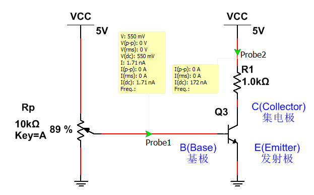
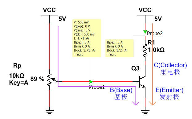
The VCC on the left side of the figure is divided by an adjustable resistor Rp and connected to the base of the transistor. The VCC on the right side is connected to the collector of the transistor through a resistor, and the emitter of the transistor is grounded. The two green arrows are probes in Multisim, which can display the current passing through the wire and the voltage on the wire (that is, the voltage relative to GND) in the yellow box.
We regard this circuit as two current paths, marked by purple and orange arrows. When Rp is adjusted to the appropriate position, a current will flow through the base, the magnitude of which is Ib, which is the current in the purple path. Due to the characteristics of the transistor, Ic, the current in the orange path, will also change according to Ib. It can also be seen from the figure that the DC current I(dc) displayed by the left and right probes are 1.71nA and 172nA (i.e., Ib and Ic) respectively.
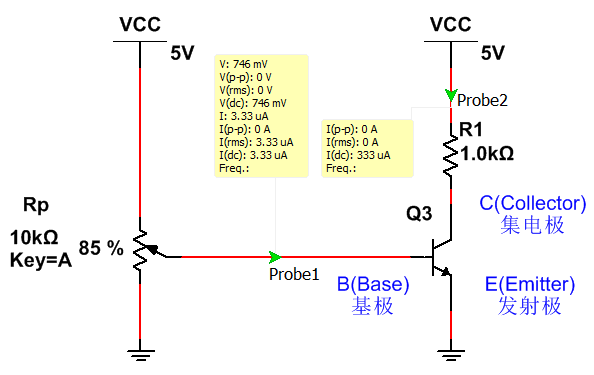
If Rp is adjusted, as shown in the figure, Ib=3.33uA, then Ic=333uA. Adjust several times and observe the results, and you will find that within a certain range, Ic=100*Ib is always approximately (in analog circuits, equal signs are often used directly to represent approximately equal, and errors are inevitable). This is exactly the amplification characteristic of the transistor. If a microphone is connected to the base and a speaker is connected to the collector, the sound signal can be amplified. Of course, some components need to be added to the actual circuit. The 100 here is the magnification of the transistor in the figure, which is a very important parameter of the transistor (the so-called parameter is the same as the resistance value of a resistor).
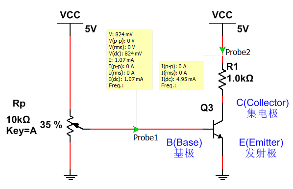
If Rp is adjusted to make the base current Ib very large, for example, Ib=1mA in the figure, then Ic is only 4.95mA, not 100mA, which does not meet the previous conditions. As mentioned above, within a certain range, Ic=100*Ib, that is, the two are proportional, which is called the linear region of the transistor, also called the amplification region. If the voltage between the base and the emitter is too large and exceeds a certain range, it will enter the saturation region of the transistor, and the value of Ic will be relatively large; conversely, if the voltage is too small, it will enter the cut-off region, in which Ic is very small, almost 0. It is precisely by using this characteristic that we can connect the IO port of the microcontroller to the base, and connect the buzzer to the collector of the transistor for control.
Note 1: The simulation circuit has great limitations and can only simulate the actual circuit to a certain extent. The actual circuit is very complex, for example, the wire has resistance, but it is difficult to consider so many factors in the design of the simulation software, and there are still some unknown problems that cannot be considered. Therefore, the simulation results can only be used as a reference. For example, in the circuit above, I found that even if I kept adjusting Rp and let the slider move directly to the 5V end, the base voltage still did not reach 5V, which is inconsistent with the actual circuit.
Note 2: As mentioned earlier, the IO port of the microcontroller uses an electronic switch, which is similar to the transistor circuit above, but the MOS tube is actually used in the microcontroller.
Note 3: In order to make the transistor work in the amplification area, a resistor is often used to keep the voltage between the base and the emitter within a certain range. This process is called the setting of the static operating point. After setting the static operating point, a small AC signal that needs to be amplified is superimposed on it (if an AC signal is added directly, it will not work in the amplification area).
Note 4: When the transistor is used as an electronic switch, although it does not work in the amplification area, it still plays the role of current amplification, but it does not meet the amplification factor relationship in the linear area. If Rp in the above figure is replaced with a fixed resistor and a thermistor whose resistance changes with temperature, if the transistor amplification factor is large enough, it can be made into a thermal switch, which can control the switch of the LED according to the temperature, and the electronic switch is named after this.
================================================== =====
Previous article:Microcontroller for Beginners (21) IO port: basic LED and button operations
Next article:Microcontroller for beginners (23) Knowledge supplement: bidirectional IO port, complementary push-pull, high impedance state
- Popular Resources
- Popular amplifiers
- Learn ARM development(16)
- Learn ARM development(17)
- Learn ARM development(18)
- Embedded system debugging simulation tool
- A small question that has been bothering me recently has finally been solved~~
- Learn ARM development (1)
- Learn ARM development (2)
- Learn ARM development (4)
- Learn ARM development (6)
 Professor at Beihang University, dedicated to promoting microcontrollers and embedded systems for over 20 years.
- LED chemical incompatibility test to see which chemicals LEDs can be used with
- Application of ARM9 hardware coprocessor on WinCE embedded motherboard
- What are the key points for selecting rotor flowmeter?
- LM317 high power charger circuit
- A brief analysis of Embest's application and development of embedded medical devices
- Single-phase RC protection circuit
- stm32 PVD programmable voltage monitor
- Introduction and measurement of edge trigger and level trigger of 51 single chip microcomputer
- Improved design of Linux system software shell protection technology
- What to do if the ABB robot protection device stops
- CGD and Qorvo to jointly revolutionize motor control solutions
- CGD and Qorvo to jointly revolutionize motor control solutions
- Keysight Technologies FieldFox handheld analyzer with VDI spread spectrum module to achieve millimeter wave analysis function
- Infineon's PASCO2V15 XENSIV PAS CO2 5V Sensor Now Available at Mouser for Accurate CO2 Level Measurement
- Advanced gameplay, Harting takes your PCB board connection to a new level!
- Advanced gameplay, Harting takes your PCB board connection to a new level!
- A new chapter in Great Wall Motors R&D: solid-state battery technology leads the future
- Naxin Micro provides full-scenario GaN driver IC solutions
- Interpreting Huawei’s new solid-state battery patent, will it challenge CATL in 2030?
- Are pure electric/plug-in hybrid vehicles going crazy? A Chinese company has launched the world's first -40℃ dischargeable hybrid battery that is not afraid of cold
- CAN bus research notes
- Show off the Jingdong E-card exchanged with E-coin
- Series shift register question
- PMOS Circuit Analysis
- CCS 7.4.0 imports routines of PDK_c667x_2_0_9
- 11 years of experience in microwave and radio frequency manufacturing
- I need a QFN24 packaged MCU with two ADCs, two serial ports, low power consumption, in stock, GD Zhaoyi Innovation has recommendations...
- Design and implementation of high-speed real-time speech recognition system based on DSP
- What is strong current & weak current? What is the difference between the two? I didn't expect the truth to be like this! ~
- EEWORLD University Hall----Live Replay: Microchip's latest SAM and PIC32 microcontroller software development platform - MPLAB? Harmony V3 introduction

 5962R9679801QCA


 京公网安备 11010802033920号