Microcontroller buzzer control program and drive circuit diagram
Source: InternetPublisher:JFET Keywords: Single chip microcomputer comprehensive control buzzer Updated: 2020/11/24
Buzzers are divided into piezoelectric buzzers and electromagnetic buzzers according to their structure. The piezoelectric buzzer produces sound from a piezoelectric ceramic piece, and the current is relatively small. The electromagnetic buzzer produces sound from a coil that is energized and vibrates, and the volume is relatively small.
According to the driving mode, it is divided into active buzzer and passive buzzer. The active and passive here do not refer to the power supply, but to the oscillation source. The active buzzer has an oscillation source inside, as shown in Figure 1. If the BUZZ pin is given a low level, the buzzer will sound directly. The passive buzzer does not have an oscillation source inside. To make it sound, it must be driven by a pulse frequency signal between 500Hz and 4.5KHz. Active buzzers are often more expensive than passive buzzers because they contain an oscillation circuit and are simple to drive and sound. They can be driven by level, while passive buzzers are cheaper. In addition, passive buzzers The sound frequency can be controlled, and there is a definite correspondence between the scale and the frequency, so the effect of "do re mi fa sol la si" can be made. It can be used to create simple music tracks, such as Birthday Song and Two Tigers etc.
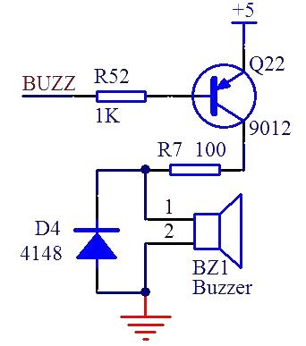
Let's take a look at the circuit in Figure 1. The buzzer current is still relatively large, so it needs to be driven by a triode, and a 100 ohm resistor is added as a current limiting resistor. In addition, a D4 diode is added, which is called a freewheeling diode. Our buzzer is an inductive device. When the transistor is turned on to power the buzzer, a conductive current will flow through the buzzer. And we know that one of the characteristics of the inductor is that the current cannot change suddenly. When it is turned on, the current gradually increases. This is no problem. However, when it is turned off, the circuit of "power supply-transistor-buzzer-ground" will If it is cut off, no current can flow. So where does the stored current go? It is consumed through the loop of D4 and the buzzer itself, thereby avoiding the reverse impact caused by the inductor current during shutdown. . Continuing the current when it is turned off, this is where the name freewheeling diode comes from.
Buzzers are often used to make beeps on devices such as computers, printers, and multimeters. The beeps are generally very simple, just make a sound. We used a program to simply make a sound at the 4KHZ frequency and the sound at the 1KHZ frequency. Program, students can study the program themselves and compare the actual effects.
#include
sbit BUZZ = P1^6; //Buzzer control pin
unsigned char T0RH = 0; //T0 high byte of reload value
unsigned char T0RL = 0; //T0 low byte of reload value
void OpenBuzz(unsigned int frequ);
void StopBuzz();
void main(){
unsigned int i;
TMOD = 0x01; //Configure T0 to work in mode 1, but do not start it yet
EA = 1;
while (1){ //Enable global interrupt
OpenBuzz(4000); //Start the buzzer at a frequency of 4KHz
for (i=0; i<40000; i++);
StopBuzz(); //Stop the buzzer
for (i=0; i<40000; i++);
OpenBuzz(1000); //Start the buzzer at a frequency of 1KHz
for (i=0; i<40000; i++);
StopBuzz(); //Stop the buzzer
for (i=0; i<40000; i++);
}
}
/* Buzzer startup function, frequ-working frequency*/
void OpenBuzz(unsigned int frequ){
unsigned int reload;//Calculate the required timer reload value
reload = 65536 - (11059200/12)/(frequ*2); //Calculate the timer reload value from the given frequency
T0RH = (unsigned char)(reload >> 8); //16-bit reload value is decomposed into high and low bytes
T0RL = (unsigned char)reload;
TH0 = 0xFF; //Set an initial value close to overflow so that the timer can start working immediately
TL0 = 0xFE;
ET0 = 1; //Enable T0 interrupt
TR0 = 1; //Start T0
}
/*Buzzer stop function*/
void StopBuzz(){
ET0 = 0; //Disable T0 interrupt
TR0 = 0; //Stop T0
}
/* T0 interrupt service function, used to control the buzzer sound */
void InterruptTimer0() interrupt 1{
TH0 = T0RH; //Reload the reload value
TL0 = T0RL;
BUZZ = ~BUZZ; //Invert the buzzer control level
}
In addition, using a buzzer to output music is just for fun and has few applications. It contains content related to scales and music scores, and the program is a bit complicated, so I won’t explain it in detail. There is only one program that can play "Two Tigers". You can download it to the board and play it to satisfy your curiosity.
plain text copy
#include
sbit BUZZ = P1^6; //Buzzer control pin
unsigned int code NoteFrequ[] = { //Midrange 1-7 and treble 1-7 corresponding frequency list
523, 587, 659, 698, 784, 880, 988, //Alto 1-7
1047, 1175, 1319, 1397, 1568, 1760, 1976 //Treble 1-7
};
unsigned int code NoteReload[] = { //Timer reload values corresponding to midrange 1-7 and treble 1-7
65536 - (11059200/12) / (523*2), //Alto 1
65536 - (11059200/12) / (587*2), //2
65536 - (11059200/12) / (659*2), //3
65536 - (11059200/12) / (698*2), //4
65536 - (11059200/12) / (784*2), //5
65536 - (11059200/12) / (880*2), //6
65536 - (11059200/12) / (988*2), //7
65536 - (11059200/12) / (1047*2), //Treble 1
65536 - (11059200/12) / (1175*2), //2
65536 - (11059200/12) / (1319*2), //3
65536 - (11059200/12) / (1397*2), //4
65536 - (11059200/12) / (1568*2), //5
65536 - (11059200/12) / (1760*2), //6
65536 - (11059200/12) / (1976*2), //7
};
bit enable = 1; //Buzzer sound enable flag
bit tmrflag = 0; //Timer interrupt completion flag
unsigned char T0RH = 0xFF; //T0 high byte of reload value
unsigned char T0RL = 0x00; //T0 low byte of reload value
void PlayTwoTiger();
void main(){
unsigned int i;
EA = 1; //Enable global interrupt
TMOD = 0x01; //Configure T0 to work in mode 1
TH0 = T0RH;
TL0 = T0RL;
ET0 = 1; //Enable T0 interrupt
TR0 = 1; //Start T0
while (1){
PlayTwoTiger(); //Play music--Two Tigers
for (i=0; i<40000; i++); //Stop for a while
}
}
/*Two Tigers music playback function*/
void PlayTwoTiger(){
unsigned char beat; //Current beat index
unsigned char note; //note corresponding to the current beat
unsigned int time = 0; //Current beat timing
unsigned int beatTime = 0; //Total time of current beat
unsigned int soundTime = 0; //The sound time required for the current beat
//Two tigers note table
unsigned char code TwoTigerNote[] = {
1, 2, 3, 1, 1, 2, 3, 1, 3, 4, 5, 3, 4, 5,
5,6, 5,4, 3, 1, 5,6, 5,4, 3, 1, 1, 5, 1, 1, 5, 1,
};
//Two tigers meter, 4 means one beat, 1 means 1/4 beat, 8 means 2 beats
unsigned char code TwoTigerBeat[] = {
4, 4, 4, 4, 4, 4, 4, 4, 4, 4, 8, 4, 4, 8,
3,1, 3,1, 4, 4, 3,1, 3,1, 4, 4, 4, 4, 8, 4, 4, 8,
};
//Use beat index as loop variable
for (beat=0; beat
while (!tmrflag); //After each timer interrupt is completed, detect and process the beat
tmrflag = 0;
if (time == 0){ //Start a new beat after the current beat is played
note = TwoTigerNote - 1;
T0RH = NoteReload >> 8;
T0RL = NoteReload;
//Calculate the total beat time. Shifting 2 bits to the right is equivalent to dividing by 4. Shifting instead of division can speed up execution.
beatTime = (TwoTigerBeat * NoteFrequ) >> 2;
//Calculate the sounding time, which is 0.75 of the total time. The shifting principle is the same as above.
soundTime = beatTime - (beatTime >> 2);
enable = 1; //Instruct the buzzer to start sounding
time++;
}else{ //If the current beat has not finished playing, process the current beat
//Reset to zero when the current duration reaches the total time of the beat,
//And increment the beat index in preparation for starting a new beat
if (time >= beatTime){
time = 0;
beat++;
}else{ //When the current duration does not reach the total time,
time++; //Accumulated time count
//After reaching the sounding time, indicate to turn off the buzzer.
//Insert a silence interval of 0.25*total time,
if (time == soundTime){
enable = 0; //Used to distinguish two consecutive beats
}
}
}
}
}
/* T0 interrupt service function, used to control the buzzer sound */
void InterruptTimer0() interrupt 1{
TH0 = T0RH; //Reload the reload value
TL0 = T0RL;
tmrflag = 1;
if (enable){ //Invert the buzzer control level when enabled
BUZZ = ~BUZZ;
}else{ //Turn off the buzzer when not enabled
BUZZ = 1;
}
}
- How to remotely control devices using ESP8266 and LPC2148
- How to build a simple tachometer using an infrared reflectance sensor
- Controlling LEDs with Multithreading via Dual-Core Programming on Raspberry Pi using MicroPython
- Design and production of radio remote control fan stepless speed regulator
- Do-it-yourself trial production of phase failure protection device
- Amplitude and phase detection leakage protection device designed and manufactured using PIC16C711A
- Design and production of no-load automatic power-off device for household power supply
- Magnetic door and window anti-theft alarm
- Delay switch made with LM431
- Bicycle anti-theft alarm
- Negative voltage generation circuit diagram
- Data transmission interface circuit design of automobile driving recorder
- Interface circuit design of SPCE061A microcontroller and fingerprint identification module
- PNP and NPN transistor switching circuits
- Homemade disinfectant circuit
- Microcontroller measurement circuit
- Multi-channel patrol detection control circuit a
- Signal input circuit a
- M62430 typical applications
- Monitoring of 8048 microcontroller by WMS7705


 京公网安备 11010802033920号