Keil's software logic analyzer (logic analyzer) usage tutorial
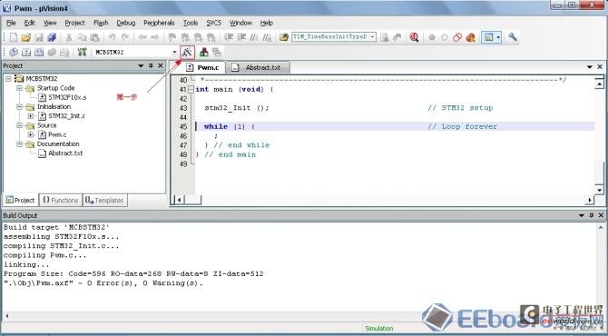
Take the stm32 CPU that comes with Keil as an example, track and observe the PWM waveform, open the stm32 Dome in the C:KeilARMBoardsKeilMCBSTM32PWM_2 directory, the first step: perform simulation configuration, as shown in the figure:
Open the Abstract.txt file in the project with a description of the project, PWM is output from PB0.8 and PB0.9, and it will be added to the software logic analyzer later.
The 'PWM' project is a simple program for the STM32F103RBT6
using Keil 'MCBSTM32' Evaluation Board and demonstrating
the use of PWM (Pulse Width Modulation) with Timer TIM4 .
Example functionality:
- Clock Settings:
- TIM4 is running at
The Timer program is available in different targets:
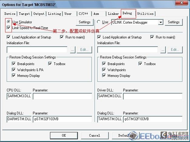
Second, select software simulation
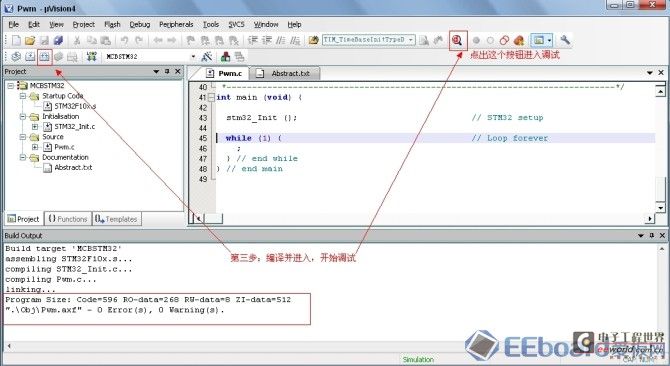
Third, compile the program. If the program is correct, the following wireframe compilation information will appear, then enter debugging and click the red "D" button, as shown in the figure below
Fourth, put the software logic analyzer and drag the waveform signal to be observed into the logic analyzer. If there is no "sysbols" label in the debugging state, click the "View" menu to pop up, and drag the signal to be observed from the "Peripheral Register" (the PWM signal output by GPIOB_IDR will be reflected from this register) into the logic analysis.
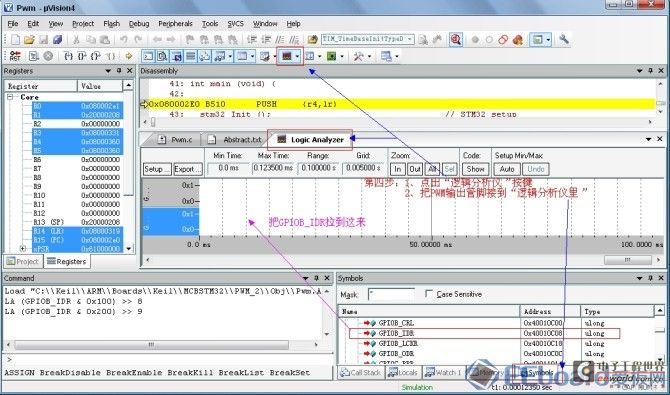
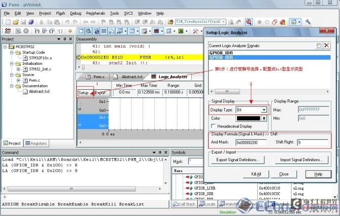
Fifth, mask the unused bits and display them in bit form. The configuration is shown in the figure
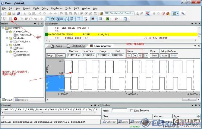
Sixth, click the "GO" button to enter full-speed operation. OK, the PWM waveform is out, and the scan time can be adjusted using IN and OUT, as shown in the figure below
Keywords:keil
Reference address:Keil's software logic analyzer (logic analyzer) usage tutorial
Take the stm32 CPU that comes with Keil as an example, track and observe the PWM waveform, open the stm32 Dome in the C:KeilARMBoardsKeilMCBSTM32PWM_2 directory, the first step: perform simulation configuration, as shown in the figure:

Open the Abstract.txt file in the project with a description of the project, PWM is output from PB0.8 and PB0.9, and it will be added to the software logic analyzer later.
The 'PWM' project is a simple program for the STM32F103RBT6
using Keil 'MCBSTM32' Evaluation Board and demonstrating
the use of PWM (Pulse Width Modulation) with Timer TIM4 .
Example functionality:
- Clock Settings:
- TIM4 is running at
The Timer program is available in different targets:
Second, select software simulation

Third, compile the program. If the program is correct, the following wireframe compilation information will appear, then enter debugging and click the red "D" button, as shown in the figure below

Fourth, put the software logic analyzer and drag the waveform signal to be observed into the logic analyzer. If there is no "sysbols" label in the debugging state, click the "View" menu to pop up, and drag the signal to be observed from the "Peripheral Register" (the PWM signal output by GPIOB_IDR will be reflected from this register) into the logic analysis.

Fifth, mask the unused bits and display them in bit form. The configuration is shown in the figure

Sixth, click the "GO" button to enter full-speed operation. OK, the PWM waveform is out, and the scan time can be adjusted using IN and OUT, as shown in the figure below

Previous article:Think from the perspective of the machine, how does the microcontroller execute the program
Next article:#ifdef DEBUG;debug();#endif
- Popular Resources
- Popular amplifiers
Recommended Content
Latest Microcontroller Articles
He Limin Column
Microcontroller and Embedded Systems Bible
 Professor at Beihang University, dedicated to promoting microcontrollers and embedded systems for over 20 years.
MoreSelected Circuit Diagrams
MorePopular Articles
- LED chemical incompatibility test to see which chemicals LEDs can be used with
- Application of ARM9 hardware coprocessor on WinCE embedded motherboard
- What are the key points for selecting rotor flowmeter?
- LM317 high power charger circuit
- A brief analysis of Embest's application and development of embedded medical devices
- Single-phase RC protection circuit
- stm32 PVD programmable voltage monitor
- Introduction and measurement of edge trigger and level trigger of 51 single chip microcomputer
- Improved design of Linux system software shell protection technology
- What to do if the ABB robot protection device stops
MoreDaily News
- Allegro MicroSystems Introduces Advanced Magnetic and Inductive Position Sensing Solutions at Electronica 2024
- Car key in the left hand, liveness detection radar in the right hand, UWB is imperative for cars!
- After a decade of rapid development, domestic CIS has entered the market
- Aegis Dagger Battery + Thor EM-i Super Hybrid, Geely New Energy has thrown out two "king bombs"
- A brief discussion on functional safety - fault, error, and failure
- In the smart car 2.0 cycle, these core industry chains are facing major opportunities!
- The United States and Japan are developing new batteries. CATL faces challenges? How should China's new energy battery industry respond?
- Murata launches high-precision 6-axis inertial sensor for automobiles
- Ford patents pre-charge alarm to help save costs and respond to emergencies
- New real-time microcontroller system from Texas Instruments enables smarter processing in automotive and industrial applications
Guess you like
- Bear Pie Huawei IoT operating system LiteOS bare metal driver transplantation 01-Explain driver transplantation using LED as an example
- 【GD32450I-EVAL】Simple oscilloscope demonstration
- [GD32E231 DIY Contest] 05. Automatic Fish Feeding Robot - PWM
- Shenzhen becomes the "world's first 5G city": challenges and business opportunities for the PCB industry
- 【Ended】 R&S Live 【PCI Express Gen 3 Conformance Test】
- Live broadcast at 10 am today [Renesas Electronics Secure IoT Suite provides you with secure cloud connection solutions
- Applications of RF Transformers
- RF FilterRF knowledge classics to understand
- 【NXP Rapid IoT Review】+Hello world!
- 5G miniaturized terminal and base station antenna technology

 KA2901D


 京公网安备 11010802033920号