1 Main content
1.1 Purpose and significance of the project
Gas chromatograph is a precision instrument with a wide range of uses. It is widely used in petroleum, chemical industry, pesticide, public security, liquor, environmental testing, health and epidemic prevention, as well as colleges and universities, scientific research departments. Since the first practical gas-liquid chromatography was created in the world in 1952, in just a few decades, gas chromatograph, as a representative of modern analytical testing instruments, has developed into an industry with a considerable production scale and has formed a discipline with quite rich testing technology knowledge. By studying the development law of gas chromatograph, it can give users useful inspiration and bring certain help to the work of relevant professionals.
1.2 Current status of domestic and foreign research
Although my country's gas chromatographs have made great progress in just two or three decades, most of the quota in this market has long been occupied by Europe, the United States and Japan. This is mainly because my country's technical indicators have not yet reached the level of first-class countries, and there are still many gaps waiting to be filled.
1.3 Main research work of this paper
Design a PIC32 series microcontroller based on Microchip, and design a gas chromatograph solution that can reach the level of foreign advanced products in terms of temperature control, constant temperature, linear temperature rise and other indicators by transplanting the ucos embedded operating system. The gas chromatograph can achieve more than 8-order linear temperature control, with a small overshoot on the temperature rise curve. When the temperature is less than 200 degrees Celsius, the error can be less than +_0.1°C, and when it is greater than 200 degrees Celsius, the error can be within +_0.1°C. The gas chromatograph control system uses a PIC32 processor to realize the processing of buttons, LCD display, communication with the host computer, and control of temperature and various function boards.
2 Overview of Gas Chromatograph Control System
2.1 Introduction to each module of the system
This system requires 595 serial-to-parallel converter, DC motor, electromagnetic relay, pressure flow sensor, AD conversion chip, host computer communication, keyboard scanning chip, EEPROM power-off protection and LCD font storage, LCD display, voltage regulator chip, etc. to drive or control. Here, these devices are briefly introduced:
2.1.1 74HC595 serial to parallel conversion
74HC595 is a silicon structure CMOS device, compatible with low voltage TTL circuit, complying with JEDEC standards. 74HC595 has an 8-bit shift register and a memory, and a three-state output function. The shift register and the memory are clocked separately. The data is input on the rising edge of SCHcp and goes to the storage register on the rising edge of STcp. If the two clocks are connected together, the shift register is always one pulse earlier than the storage register. The shift register has a serial shift input (Ds), a serial output (Q7'), and an asynchronous low-level reset. The storage register has a parallel 8-bit bus output with three states. When OE is enabled (low level), the data of the storage register is output to the bus.
2.1.2 DC Motor
DC motors have more advantages than AC motors in terms of stability, because their current is stable and they can adjust the speed very smoothly. Therefore, most precision instruments use DC motors, and DC motors can also be used for speed measurement. In this system, a four-phase DC stepper motor is used to accurately control the closing of the back door.
2.1.3 Electromagnetic relay
This system uses a single-chip microcomputer to control the system, and the controlled devices are mostly high-power devices. However, the single-chip microcomputer is a weak current device, which generally works at a voltage of 5V or even lower, and the driving current is below the mA level. To use it in some high-power occasions, there must be a "power drive" link to connect it. Commonly used power drives include transistor drive and relay drive. Among them, relay drive is a typical and simple power drive link. Relay drive has two meanings: one is to drive the relay, because the relay itself is a power device for the single-chip microcomputer; the other is that the relay drives other loads such as intermediate relays, contactors, and motors. Therefore, the relay drive is the interface between the single-chip microcomputer and other high-power loads.
2.1.4 Pressure flow sensor
Two-way flow meter analog signal input: flow 1: (nitrogen/hydrogen); flow 2: (nitrogen/hydrogen);
The two-way sensor uses Honeywell AWM3100V, 3PIN, working voltage 10V, Output voltage = 1.00_+0.5VDC when there is no gas input, the output voltage changes linearly with the input gas flow, and the nitrogen/hydrogen ratio needs to be corrected for different ratios, air = nitrogen = 1.0; hydrogen = 0.7;
Two-way pressure gauge: Honeywell 26PCF, 4PIN, working voltage 10V, measurable pressure range 0-100psi and linearly proportional to the input gas flow rate, full scale output 100mv, sensitivity 1mv/psi.
2.1.5 AD conversion chip
The AD conversion chip uses ADS1248. TI's ADS1246, ADS1247 and ADS1248 are highly integrated 24-bit precision ADCs with built-in reference voltage, programmable constant current source, internal crystal oscillator, internal analog switch switching, integrated low-noise programmable gain amplifier (PGA), precision Delta-Sigma ADC with single-cycle digital filter setting and oscillator, forming a complete temperature/bridge sensor application including thermal coupling, thermistor, RTD and stress measurement front-end solution.
2.1.6 Host computer communication
An operation interface was made using LabView and connected to the computer through the serial port, so that the gas chromatograph system can be controlled not only through real buttons but also through remote control of the computer, which is convenient for users.
2.1.7 Keyboard Scanning Chip
Since the control system of the gas chromatograph is relatively complex and has many buttons, in order to save the IO port of the CPU, a key scanning chip is used to accept the key value. ZLG7289B is designed by Guangzhou Zhou Ligong Single Chip Microcomputer Development Co., Ltd. It has an SPI serial interface function and can simultaneously drive an 8-bit common cathode digital tube (or 64 independent LEDs) intelligent display driver chip. The chip can also be connected to a keyboard matrix with up to 64 keys. A single chip can complete all the functions of LED display and keyboard interface. ZLG7289B contains a decoder inside, which can directly accept BCD code or hexadecimal code, and has 2 decoding modes at the same time. In addition, it also has a variety of control instructions, such as blanking, flashing, left shift, right shift, segment addressing, etc. ZLG7289B has a chip select signal, which can easily realize more than 8-bit display or more than 64-key keyboard interface. Typical applications: instrumentation, industrial controllers, bar displays, control panels, etc.
2.1.8 EEPROM power-off protection and LCD font storage
The EEPROM module is divided into two parts:
The first part is the storage of the LCD font library. Because the LCD used is a large 320*240 LCD, the RAM of the PIC is definitely not enough. Therefore, an AT24C512 64K EEROM is added to the periphery to store the font library. The AT24C512 provides 524,288 bits of serial electrically erasable and programmable read-only memory (EEPROM). The cascade function of the device allows up to 4 devices to share a common two-wire bus. The device is suitable for necessary uses in many industrial and commercial applications that require low power consumption and low voltage operation. These devices are available in space-saving 8-pin PDIP, 8-pin SOIC EIAJ 8-pin JEDEC SOIC packages, 8-pin TSSOP packages, 8-pin lead-free arrays and 8-pin packaged SAP. In addition, the entire family is available and can be used in 2.7 (2.7 to 5.5V) and 1.8V (1.8V to 3.6V) versions.
The second part is the power-off protection part, which uses the EEROM inside the PIC microcontroller to implement passwords, temperature setting values, detection parameters and other data. The data EEPROM non-volatile memory is an array that has independent RAM and program from the data memory, that is, the data is used for long-term storage of long-term projects. Whether in the mapped register file or program storage space, the special function register is indirectly solved through the register. The EEPROM is readable and writable in normal operation over the entire VDD range
2.1.9 LCD Display
Using Jinpeng's OCM240*320 LCD, it is suitable for medium-sized dot matrix LCD displays. It can provide all the control signals required for LCD display drivers and external display memory, and it also has a built-in character library, so only a few external devices are needed to obtain a flexible and low-power display system.
2.1.10 Voltage Regulator Chip
Gas chromatograph has high requirements on voltage stability, so two voltage regulator chips are used: TL431 to provide 10V voltage regulation and AS1117 to provide 3.3V voltage regulation.
The TL431 produced by Texas Instruments (TI) is a three-terminal adjustable shunt reference source with good thermal stability. Its output voltage can be arbitrarily set to any value from Vref (2.5V) to 36V using two resistors (as shown in Figure 2). The typical dynamic impedance of this device is 0.2Ω, and it can be used to replace the Zener diode in many applications, such as digital voltmeters, op amp circuits, adjustable voltage power supplies, switching power supplies, etc.
AS1117 is a low voltage dropout linear regulator. When outputting 1A current, the input-output voltage difference is typically only 1.2V. In addition to providing a variety of fixed voltage versions (output can be 1.8V, 2.5V, 3.3.V, 5V), AS1117 also provides an adjustable output version, which can provide an output voltage range of 1.25V-13.8V.
2.2 System overall framework
This system is designed to meet the requirements of gas chromatograph control, and fully considers its economy and reliability, and can truly achieve the requirements of gas chromatograph control. According to the overall functions to be achieved by the system, the system is mainly responsible for key detection, LCD display and communication with the host computer; control the work of each functional module, temperature collection calculation and control, pressure flow collection, etc. [page]
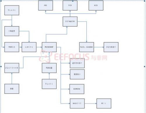
1. LCD, buzzer, and valve are directly controlled by the CPU IO port
2. The keyboard value is collected by the chip ZLG7289B. This chip can recognize up to 64 keys.
3. The circuit expands a serial port for host computer control, and the level conversion chip uses max232.
4. An EEPROM is added, each with a capacity of 64K, which is controlled by the IO port of the CPU and uses the IIC bus control
5. The CPU chip expands the IO port through the 74HC595 chip, and uses the IO port expanded by 74HC595 to control FID, ECD, and TCD;
6. In the temperature sampling part, PT100 is used as the temperature sensor, and a bridge circuit is formed with PT100 to convert the temperature into voltage, which is amplified by LM324 and sent to the analog input port of the CPU. The constant voltage circuit of Pt100 is composed of TL432;
7. The pressure analog quantity is amplified by LM324 and transmitted to the CPU analog port. The flow analog quantity is directly sent to the CPU IO port. The constant voltage circuit of these two parts is composed of TL431.
8. The motor part uses TL521 optocoupler chip to isolate the CPU IO port and the stepper motor interface, and does not use the CPU IO port to directly control the stepper motor interface, which plays a role in safety and anti-interference. Use ULN2803 chip to reverse drive the motor;
3 System Hardware Design
This chapter introduces the hardware design and implementation of each control module in sections. The system hardware is divided into the following functional modules according to function: 595 serial-to-parallel module, DC motor module, electromagnetic relay module, pressure flow sensor module, AD conversion chip module, host computer communication module, keyboard scanning chip module, EEPROM power-off protection and LCD font storage module, LCD display module, and voltage regulator chip module. In the design of each module, its working principle, design concept and implementation method are described in detail.
3.1 MCU module design
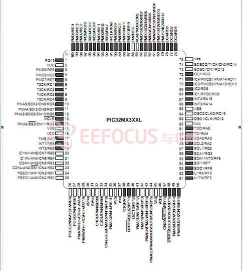
As the microprocessor of the system, the performance of the single-chip microcomputer is very critical to the entire system. Nowadays, there are many companies in the world that can produce single-chip microcomputers. With the rapid development of ultra-large-scale integrated circuits, the functions of single-chip microcomputers are becoming more and more powerful, and the computing speed is increasing. 32-bit and 64-bit single-chip microcomputers have appeared one after another. According to the actual system needs and the cost-effectiveness of the product, this system uses the 32-bit single-chip microcomputer PIC32F460F produced by Microsoft as the control chip of the system. Microchip's PIC32MX4 series is a high-performance general-purpose and USB 32-bit flash microcontroller (MCU). The following introduces their main functions [3] :
• MIPS32® M4K™ 32-bit core with 5-stage pipeline
• Frequency up to 80 MHz
• 1.56 DMIPS/MHz performance with zero wait state flash access (Dhrystone 2.1)
• Single-cycle multiplication unit and high-performance division unit
• MIPS16e™ mode enables up to 40% code compression
• Two sets of 32 32-bit core file registers each to reduce interrupt latency
• Prefetch cache module accelerates execution from flash memory
• Operating voltage range is 2.3V to 3.6V
• 32 KB to 512 KB of Flash (plus an additional 12 KB of boot Flash)
• 8 KB to 32 KB of SRAM memory
• Pin compatible with most PIC24/dsPIC® devices
• Multiple power management modes
• Multiple interrupt vectors with individually programmable priority levels
• Fail-Safe Clock Monitor Mode
• Configurable watchdog timer with on-chip low-power RC oscillator to ensure reliable device operation
• 2 programming and debugging interfaces:
- Two-wire interface for non-preemptive access to and from applications
Real-time data exchange
-4-wire MIPS® standard enhanced JTAG interface
• Hardware-based non-preemptive instruction tracing
• Boundary scan features compliant with IEEE Standard 1149.2 (JTAG)
• 10-bit ADC with up to 16 channels:
- Conversion rate of 1000 ksps
- Convertible during Sleep and Idle modes
The pin diagram of PIC32MX460F is as follows:
3.2 595 serial-to-parallel module control module design
3.2.1 Principle and function of 595 serial-to-parallel module
In this system, due to the large number of control modules, only three detection modules (FID, ECD, TCD) require more than 72 control ports, so 74HC595 is used for serial-to-parallel conversion to save IO port resources. One IO port is used to continuously send out 24 bits, and three 74HC595s are cascaded to control each module.
3.2.2 Module design and implementation

Figure 2 74HC595 control module circuit diagram
As shown in the figure, this is a part of the three detection modules, which is composed of three 595 cascades. The microcontroller only provides three IO pins, which can control 24 bits to complete the function of the FID module.
74HC595 is a silicon-structured CMOS device that is compatible with low-voltage TTL circuits and complies with JEDEC standards. 74HC595 has an 8-bit shift register and a memory with a three-state output function. The shift register and memory are clocked separately. Data is input on the rising edge of SCHcp and enters the storage register on the rising edge of STcp. If the two clocks are connected together, the shift register is always one pulse earlier than the storage register. The shift register has a serial shift input (Ds), a serial output (Q7'), and an asynchronous low-level reset. The storage register has a parallel 8-bit bus output with a three-state function. When OE is enabled (low level), the data of the storage register is output to the bus. [page]
3.3 Solenoid valve control module design
3.3.1 Principle and function of solenoid valve
Solenoid valves are industrial equipment controlled by electromagnetics, used in industrial control systems to adjust the direction, flow, speed and other parameters of the medium. There are many types of solenoid valves, and different solenoid valves play a role in different positions of the control system. The most commonly used ones are check valves, safety valves, directional control valves, speed control valves, etc. Solenoid valves are controlled by electromagnetic effects, and the main control methods are controlled by transistors and relays. In this way, solenoid valves can be used with different circuits to achieve the desired control, and the accuracy and flexibility of control can be guaranteed.
Solenoid valves are divided into three categories in principle: direct-acting, step-by-step direct-acting and pilot-operated. The solenoid valve to be controlled in this design is a direct-acting solenoid valve, and its principle is shown in Figure 2-4: when the power is on, the electromagnetic coil generates electromagnetic force to lift the closing element from the valve seat, and the valve opens; when the power is off, the electromagnetic force disappears, the spring presses the closing element onto the valve seat, and the valve closes.

Figure 3 Schematic diagram of the action of a single electric direct-acting solenoid valve
1-electromagnet; 2-valve core
3.3.2 Module design and implementation
This system needs to control multiple solenoid valves to realize a series of functions such as sensitivity, polarity, coarse and fine adjustment of the gas chromatograph. The design of this module is shown in Figure 2-5. The driving signal is amplified by the transistor common-emitter amplifier circuit, and a total of four channels drive four solenoid valves respectively. This design only needs to control the switch of the solenoid valve at a fixed time. The transistor drive can already meet the system requirements, so there is no need to use a relay circuit to control it. The circuit diagram of the solenoid valve control part shows that the power supply mode of the solenoid valve is VCC2 for the positive pole, but after passing through the transistor, the negative pole is GND, so a loop cannot be formed. In order to solve this problem, a high-current diode is added between GND and GND2, as shown in Figure 2-6. This can not only make the solenoid valve work normally, but also ensure that the solenoid valve operation interferes with the power supply of the single-chip computer system.

Figure 4 Solenoid valve control circuit diagram
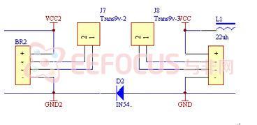
Figure 5 Loop diode circuit diagram
3.4 Motor Control Module Design
3.4.1 DC motor principle and control method
The working principle of a DC motor [8] is as follows: As shown in Figure 2-7 (a), a DC current flows in from brush A, passes through coil abcd, and flows out from brush B. According to the law of electromagnetic force, the current-carrying conductors ab and cd are acted upon by electromagnetic force, the direction of which can be determined by the left-hand rule. The force on the two conductors forms a torque, causing the rotor to rotate counterclockwise. If the rotor rotates to the position shown in Figure 2-7 (b), brush A contacts commutator segment 2, brush B contacts commutator segment 1, and DC current flows in from brush A. The direction of flow in the coil is dcba, and it flows out from brush B. At this time, the direction of electromagnetic force on the current-carrying conductors ab and cd can also be determined by the left-hand rule, and the torque they generate still causes the rotor to rotate counterclockwise.

Figure 6 Schematic diagram of DC motor
The external power supply is DC, but due to the action of the brushes and commutator, the current flowing through the coil is AC, and the direction of the torque generated is unchanged. The energized coil rotates under the action of force in the magnetic field. When it passes the equilibrium position, the commutator changes the direction of the current in the coil so that it can rotate continuously. In practice, the winding on the rotor of a DC motor is not composed of one coil, but of multiple coils connected together to reduce the fluctuation of the electromagnetic torque of the motor.
The control of DC motors is generally controlled by relays, thyristors, etc. Here, it is necessary to control the start, stop, and forward and reverse rotation of the motor, but the control frequency is not high and speed regulation is not required, so relay control is selected. Each motor uses two DC 12V relays to control the two-phase power supply to start, stop, and forward and reverse.
3.4.2 Module design and implementation
In this control module, the DC motor is used to control the forward and backward movement of the back of the massage chair and the up and down movement of the legs. It requires relatively smooth movement, so a 24V DC motor is used. Since the system does not require speed regulation, it only needs to control the forward and reverse rotation of the motor, so the use of relays to control the power supply can meet the requirements. The forward and reverse rotation of the motor is achieved by reverse connection of the power supply, so the two power lines of the DC motor must have the opportunity to connect the positive and negative power supply. Each motor needs two relays to control the two power lines. Only in this way can the forward and reverse rotation of the motor be effectively controlled.
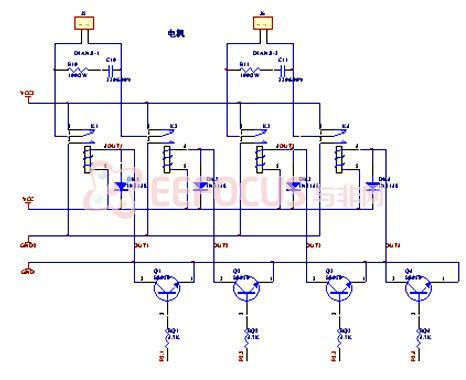
Figure 7 Motor control circuit diagram
As shown in Figure 2-8, when the relay K1 is closed and the power is turned on, K2 is disconnected and grounded, the motor 1 rotates forward, the relay K1 is disconnected and grounded, K2 is closed and the power is turned on, the motor 1 rotates reversely, and the motor stops in other states; similarly, K3 and K4 control the forward, reverse and stop of motor 2. The parallel capacitor in the motor control circuit is to allow the motor to generate a starting torque, so that the motor can be ensured to rotate automatically after power is supplied. In addition, when the DC motor rotates, the rotor current is supplied to the rotor winding through the brush and commutator contact. During operation, there are sparks at the contact point and electromagnetic waves are generated. The parallel capacitor can also eliminate or reduce electromagnetic interference.
3.5 Other module designs
3.5.1 Pressure flow sensor module design Module design and implementation
Two-way flow meter analog signal input: flow 1: (nitrogen/hydrogen); flow 2: (nitrogen/hydrogen);
The two-way sensor uses Honeywell AWM3100V, 3PIN, working voltage 10V, Output voltage = 1.00_+0.5VDC when there is no gas input, the output voltage changes linearly with the input gas flow rate, note that the nitrogen/hydrogen ratio needs to be corrected for different ratios, air = nitrogen = 1.0; hydrogen = 0.7
Two-way pressure gauge (Honeywell 26PCF, 4PIN, working voltage 10V, measurable pressure range 0-100psi and linearly proportional to input gas flow, full scale output 100mv, sensitivity 1mv/psi) [page]
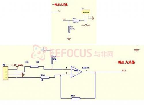
Figure 8 Pressure flow control circuit diagram
3.5.2 Key Circuit Design
This system uses 31 keys in total, which is a lot of keys, so a scanning chip is used to save IO resources. At the same time, a wire controller interface is reserved on the main control board, which can be used for function expansion when necessary and can be changed to a matrix keyboard at any time. This improves the scalability and upgradeability of the system.
3.5.3 Buzzer circuit design
The buzzer circuit is used for alarm or prompt. The buzzer uses a 5V DC buzzer and is driven by a transistor. The control circuit diagram is as follows
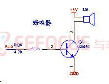
Figure 9 Buzzer circuit diagram
3.5.4 EEPROM module circuit design
AT24C512 is used to store LCD fonts, using the IIC bus.
3.6 Chapter Summary
In the process of hardware circuit design, typical circuits should be used as much as possible. The information of typical circuits is easier to collect, and the correctness and reliability of the circuits are guaranteed, which also shortens the debugging time of the hardware. However, when using typical circuits, the circuits should also be modified according to the actual situation of this design. Because this paper is a scheme design, only simple schematics are listed, and the next step will be to implement them in the graduation design.
4 Debugging and Summary
The system uses Microchip's PIC32 series microcontroller as the microprocessor chip, and controls the corresponding functional modules according to the detected key status to perform FID, ECD, TCD and other tests. The focus of this design is to use Microchip's PIC32 series microcontroller to complete the control of the entire system. Including buttons, motors, serial-to-parallel conversion; LCD display; EEPROM storage (including LCD font library and power-off protection); temperature setting, LabView echo; air pressure and flow measurement and echo; control of each module (including FID, ECD, TCD).
The instrument uses PIC32 series single-chip microcomputer as microprocessor chip, PT100 as temperature sensor, simple two-wire structure, and then converts temperature into digital quantity through differential circuit composed of 24-bit high-precision AD-ADS1248. The single-chip microcomputer controls the on and off of the thyristor to control the heating and stopping of the heating wire. The temperature control accuracy is achieved in hardware with an error less than +_0.1°C. In the software design, it communicates with the host computer in real time. LabView is used to make an operation interface, which is connected to the computer through the serial port, so that the control of the gas chromatograph system can be controlled not only through real buttons, but also through remote control of the computer, which is convenient for users. By transplanting the ucos operating system and using the fuzzy PID algorithm with the support of the operating system, the proportional, integral and differential parameters of the PID algorithm can be adaptively adjusted to ensure that the temperature control accuracy error is less than +_0.1°C, which is relatively advanced in China.
The system has the following features:
1. Reliability: The reliability of the system is the first priority. The reliability of the system must be fully considered in the design. The monitoring system has good isolation performance, and the control circuit power supply and equipment working power supply are isolated;
2. Versatility: The motors and solenoid valves controlled by the control system are commonly used components in automation equipment and can become control panels for other equipment through software upgrades;
3. Economical: The system adopts practical technology and equipment to achieve the goal of reducing the overall project cost, making the system have a good cost-effectiveness;
4. Practicality: Use general control methods and intelligent design to minimize the complexity of system operation and ensure stable system operation and simple maintenance.
Previous article:Implementation of wireless self-service ordering system based on PIC32, including schematic diagram and circuit diagram
Next article:Solar water heater constant temperature water mixing device based on PIC32
- Popular Resources
- Popular amplifiers
 Professor at Beihang University, dedicated to promoting microcontrollers and embedded systems for over 20 years.
- LED chemical incompatibility test to see which chemicals LEDs can be used with
- Application of ARM9 hardware coprocessor on WinCE embedded motherboard
- What are the key points for selecting rotor flowmeter?
- LM317 high power charger circuit
- A brief analysis of Embest's application and development of embedded medical devices
- Single-phase RC protection circuit
- stm32 PVD programmable voltage monitor
- Introduction and measurement of edge trigger and level trigger of 51 single chip microcomputer
- Improved design of Linux system software shell protection technology
- What to do if the ABB robot protection device stops
- Keysight Technologies Helps Samsung Electronics Successfully Validate FiRa® 2.0 Safe Distance Measurement Test Case
- Innovation is not limited to Meizhi, Welling will appear at the 2024 China Home Appliance Technology Conference
- Innovation is not limited to Meizhi, Welling will appear at the 2024 China Home Appliance Technology Conference
- Huawei's Strategic Department Director Gai Gang: The cumulative installed base of open source Euler operating system exceeds 10 million sets
- Download from the Internet--ARM Getting Started Notes
- Learn ARM development(22)
- Learn ARM development(21)
- Learn ARM development(20)
- Learn ARM development(19)
- Learn ARM development(14)
- I'm new to PCB, please give me some guidance, thank you
- How to keep the IO port in BlueNRG-1 sleep mode
- 2011 eNewsletter
- Which hot air gun and soldering station is worth having?
- Wi-Fi filter design tips (recommended for collection)
- One picture to understand: Manned spacecraft are booming in various countries, who is leading the way?
- TI Designs – Precision file question about Bode plots
- IoT Project Collection 2: Which one would you like to build?
- Award-winning live broadcast: Application of Weidmuller products in the semiconductor industry is in progress!
- What is the difference between edge triggering (rising edge, falling edge) and level triggering (high level and low level) in digital circuits?

 OPA37BJ/883B


 京公网安备 11010802033920号