With the improvement of people's living standards, flowers are gradually favored by people, cultivating sentiment and purifying the air. Using a single-chip microcomputer, a home intelligent watering device is designed to realize automatic watering, saving manpower and facilitating people's business trips without affecting the growth of flowers. If you are at home, you can also turn off the watering device and water the flowers manually. The watering device can be set in two ways, one is timed quantitative watering, and the other is watering according to humidity. Which method is used is controlled by buttons or infrared remote control. When using timed quantitative watering, the digital tube displays the time and water flow time. When watering according to humidity, the digital tube displays the current humidity.
1 Overall Design
An automatic watering device is designed using the AT89S52 single-chip microcomputer. For different flowers, this intelligent watering device is set to two modes: one is to water flowers at a fixed time and quantity, and the other is to use a humidity sensor to detect the humidity of flowers (can also be used for vegetables, etc.). The collected humidity is transmitted to the single-chip microcomputer chip. The single-chip microcomputer controls whether to water according to the humidity. If watering is required, a pin p2.0 of the single-chip microcomputer is set to a high level, so that the relay coil is energized, the open contacts are closed, and the solenoid valve is opened to achieve automatic watering at a fixed time and quantity. When the set time is reached, the solenoid valve is automatically closed, and the water flow time is adjustable. A digital tube is installed on it, and there is a button to set the length of watering time according to the different water requirements of different flowers. The length of watering time can be displayed on the digital tube; if the humidity is detected to be sufficient, p2.0 remains at a low level and the solenoid valve is not opened. Which method is used is controlled by buttons or infrared remote control. When using fixed-time quantitative watering, the digital tube displays the time and water flow time. When watering according to humidity, the digital tube displays the current humidity.
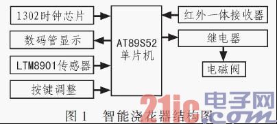
The technical solution adopted by this technology is: use the single-chip microcomputer to realize automatic control, first detect which method is used to water the flowers, if it is timed and quantitative watering, start watering the flowers at the specified time, and water the flowers according to the set watering time; if it is based on humidity control whether to water, set a pin of the single-chip microcomputer to a low level, the humidity sensor detects the humidity and transmits it to the single-chip microcomputer chip. When it detects that the humidity is insufficient, the pin of the single-chip microcomputer becomes a high level, the relay is attracted, the normally open contact is closed, and the solenoid valve coil is energized. At this time, the solenoid valve is closed and disconnected, and water flows through to water the flowers. Its structure is shown in Figure 1.
2 Hardware Design
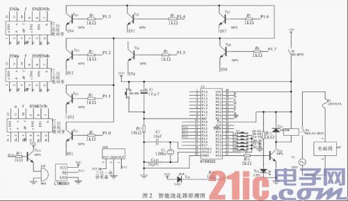
The hardware circuit is composed of a single-chip microcomputer, a humidity sensor, a relay, a solenoid valve, a digital tube, a 1302 chip, a button, an infrared remote control receiver, etc. Note that if the solenoid valve is placed too close to the single-chip microcomputer, it will not work properly. The solution is: 1) The solenoid valve is away from the single-chip microcomputer; 2) Add resistors and capacitors. The method of adding resistors and capacitors is adopted here, which makes it convenient to concentrate the components and the controller is relatively small. The schematic diagram of the smart watering device is shown in Figure 2.
2.1 Timed and quantitative watering method
Timed quantitative watering means starting watering at a specified time every day, setting the watering time, for example, 1 minute, and stopping watering after 1 minute. Specific hardware: 2 three-digit common anode digital tubes and 1 two-digit common anode digital tube are installed to display the time and the length of watering time. The buttons control the time adjustment and time setting adjustment, and there is a button to set the length of watering time according to the different water requirements of different flowers, which is displayed on the digital tube. The 1302 chip realizes time retention, and the time is not affected when the power is off. [page]
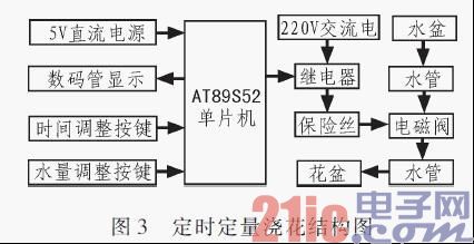
Here, it can be assumed that the flowers are watered automatically at 7:20 every morning, and the watering time is 1 minute. At 7:20 in the morning, the single-chip microcomputer controls the intelligent watering device to start watering the flowers. The single-chip microcomputer P2.0 pin is connected to the relay, and the relay is connected to the solenoid valve. The solenoid valve controls the water flow. At 7:20, a command is given to the single-chip microcomputer, setb 02.0, and the three-pole tube is turned on. In this way, the relay coil has current passing through, and the corresponding normally open contact is closed, so that the solenoid valve coil is energized. At this time, the solenoid valve changes from closed to open, and water flows through to water the flowers. When the 1 minute is up, a command clr p2.0 is given to the single-chip microcomputer, so that the single-chip microcomputer P2.0 pin outputs a low level, the transistor is cut off, the relay coil has no current passing through, the normally open contact is restored to open, and the solenoid valve coil loses power. At this time, the solenoid valve is closed and the water flow stops. The time here is displayed on the digital tube. It can be adjusted by key control. At the same time, the watering time can also be set by key, and the length of the watering time can also be adjusted by key. At the same time, a 1302 chip is added to prevent the time from being affected when the power is off, and to avoid the need to readjust the time after each power outage. Figure 3 is a diagram of the structure of timing and quantitative watering.
2.2 Humidity Control Watering Method
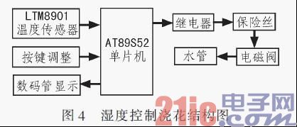
First, set the humidity by pressing the button. The humidity sensor selected here is the LTM8901 humidity sensor. The LTM8901 is a digital temperature and humidity probe specially provided for users to design their own products. Its humidity measurement range is 1% to 99%RH, the resolution is 0.5%RH, and the measurement accuracy is ±3.0%RH (typical value); the temperature measurement range is -25 to +60℃, the resolution is 0.0625℃, and the measurement accuracy is ±0.5℃; the typical response time is 5 s; the operating voltage range is 4.5 to 5.5 V. The LTM8901 directly outputs the measurement results as digital signals, which are serially transmitted to the microcontroller through the "one-line bus". There is no need for analog-to-digital conversion, which reduces components and is simple and convenient. The humidity is detected by the LTM8901 humidity sensor and transmitted to the microcontroller for processing. The humidity is displayed on the digital tube. When the humidity is lower than the set value, a command is given to the microcontroller, seth p2.0, and current flows through the relay coil. The corresponding normally open contact closes, and the solenoid valve coil is energized. At this time, the solenoid valve changes from closed to open, and watering is carried out. When it is equal to or higher than the set value, clr p2.0, the relay coil loses power, the corresponding normally open contact is disconnected, the solenoid valve coil loses power, the valve closes, and water cannot flow through, stopping watering. The humidity control watering structure is shown in Figure 4.
2.3 Mode Setting
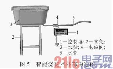
It can be set by pressing the button manually. Pressing an odd number of times sets the watering mode to timed quantitative watering, and pressing an even number of times sets the watering mode to watering according to humidity. The watering mode can also be set by infrared remote control. The transmitter uses a TV remote control, and the receiving circuit uses a trinity receiver to receive the signal. The 1st pin of the trinity receiver is grounded, the 2nd pin is connected to the power supply, and the 3rd pin (signal pin) is connected to an I/O pin of the microcontroller. When the signal comes, it is decoded and processed differently. When the signal is received once, the flowers are watered according to timed quantitative watering, and when the signal is received again, the flowers are watered according to humidity. According to the number of times pressed, the odd number of times uses the timed quantitative watering mode, and the even number of times uses the humidity control watering mode. This is mainly for different flowers. When the signal is received, the light-emitting diode flashes for 30 seconds. The buzzer sounds for 10 seconds to remind you. The external structure of the intelligent watering device is shown in Figure 5.
3 Programming
3.1 Programming ideas
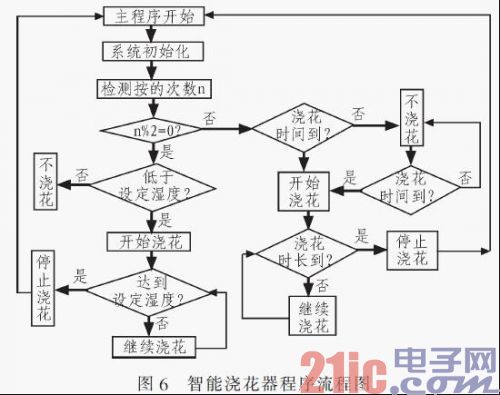
1) Mode setting: The working mode is determined by detecting the number of times the button is pressed. Let the number of times pressed be n. The first time it is pressed, n=1. Each time n is pressed, it increases by one. When it reaches a certain number of times, 1,000, n starts from 0. If (n=10000) (n=0); the pin connected to the button is high at the beginning, and once it is pressed, it becomes low. The number of times the high level changes to the low level is detected to detect whether it is pressed. If it is pressed an odd number of times, the flowers are watered by timing and quantity. If it is pressed an even number of times, the flowers are watered by detecting humidity. If (n%2=0) is used to judge, if the remainder is 0, it means an even number of times, otherwise it is an odd number of times. [page]
2) To water the flowers at a fixed time and quantity, first write the time display program, and then determine whether it is the set watering time and how long the watering time should be.

In the program, c represents hours, b represents minutes, a represents seconds, and w represents the set time. First, if the time is not up, the p2.0 pin is 0 (P2_0=0), and no watering occurs. When the time is up (if (c==7&b==20&0
3) Humidity detection watering first starts the conversion, reads the humidity detected by LTM8901, makes a comparison and judgment, and finally executes.
3.2 Flowchart
The program flow chart of the intelligent watering device is shown in Figure 6.
4 Conclusion
This paper introduces the design of a household intelligent watering device, conducts hardware design and program analysis, and has been made into a physical object with good use effect. The household intelligent watering device has a wide range of uses. By changing the program, it can also be used as a timer switch, dormitory lighting system, temperature-controlled plastic greenhouse, etc. This household intelligent watering device can also be used for intelligent watering of lawns and vegetables, etc., by removing the water tank and directly connecting the faucet. The innovation of the system design lies in the realization of different ways of automatic watering and the retractable water pipe, which helps to change the distance between the flower pot and the water source; the problem that needs to be paid attention to in the design process is to prevent the microcontroller from resetting when the solenoid valve is closed, and add resistors and capacitors for buffering. The capacitor selected in this system is 400 V withstanding voltage.
Previous article:Design and implementation of wireless transmission system based on USB
Next article:Application of STC89C58RD+ MCU in the Design of MP3 Player
Recommended ReadingLatest update time:2024-11-15 17:33


 Professor at Beihang University, dedicated to promoting microcontrollers and embedded systems for over 20 years.
- LED chemical incompatibility test to see which chemicals LEDs can be used with
- Application of ARM9 hardware coprocessor on WinCE embedded motherboard
- What are the key points for selecting rotor flowmeter?
- LM317 high power charger circuit
- A brief analysis of Embest's application and development of embedded medical devices
- Single-phase RC protection circuit
- stm32 PVD programmable voltage monitor
- Introduction and measurement of edge trigger and level trigger of 51 single chip microcomputer
- Improved design of Linux system software shell protection technology
- What to do if the ABB robot protection device stops
- Keysight Technologies Helps Samsung Electronics Successfully Validate FiRa® 2.0 Safe Distance Measurement Test Case
- Innovation is not limited to Meizhi, Welling will appear at the 2024 China Home Appliance Technology Conference
- Innovation is not limited to Meizhi, Welling will appear at the 2024 China Home Appliance Technology Conference
- Huawei's Strategic Department Director Gai Gang: The cumulative installed base of open source Euler operating system exceeds 10 million sets
- Download from the Internet--ARM Getting Started Notes
- Learn ARM development(22)
- Learn ARM development(21)
- Learn ARM development(20)
- Learn ARM development(19)
- Learn ARM development(14)
- Classic time series
- STM32 built-in DAC output voltage amplified to drive piezoelectric ceramics
- TI - Delivering Ultra-High Power Density for 100W USB Power Delivery Adapters
- What challenges does the epidemic bring to engineers?
- Seeking routines for driving LPS33HW pressure sensor of STM32F103 series
- Just to tell you a joke, I spent the whole afternoon trying to write a for loop properly.
- Three solutions for implementing motor control design, which one is better?
- 【GD32307E-START】+Serial communication function test
- [HPM-DIY] HPM6750 openmv transplantation is successful, using cherryusb as repl interaction
- The software engineer said he doesn't know how to use GPIO to simulate I2C. Is he a newbie?

 西门子S7-12001500 PLC SCL语言编程从入门到精通 (北岛李工)


 京公网安备 11010802033920号