1 Overall Design
The personnel registration and entry system is designed for the exhibition hall. The system is mainly composed of five parts: single-chip microcomputer control, signal acquisition, camera, LCD display, and power supply. The hardware structure diagram is shown in Figure 1. When someone wants to enter the hall, the signal collected by the infrared device will be sent to the single-chip microcomputer, which processes the collected signal and controls the camera to take pictures of the people entering the hall, while recording the entry time, and then displays the number of people in the hall on the LCD screen. When someone leaves the library, the system works the same as when someone is inside.

The functions that this system can realize are:
1) Display the number of people in the museum;
2) Take photos of people entering and leaving the museum;
3) When the museum is full, there will be obvious signs to prohibit entry;
4) Record the time when people enter and leave the museum.
The MSP430 series microcontroller is used as the control chip, the signal acquisition circuit uses an infrared integrated tube as the main component, the camera is used for taking pictures, the display part uses an LCD12864 liquid crystal display, and the power supply part uses a homemade +5 V regulated power supply. Compared with the 51 series microcontroller, the MSP430 microcontroller has stronger processing power, convenient peripheral circuits, and reset function. It is a new generation of microcontrollers with high speed/low power consumption/super strong anti-interference. Its interrupts, timing, and I/O outputs are far more than the 51 series, and the internal integrated comparison amplifier and multi-channel AD determine that it has strong scalability, so this system uses the MSP430F149 microcontroller as the control chip. Compared with pressure sensors, infrared sensors are non-contact sensors. They have much less loss than pressure sensors and have the advantages of fast response speed, long service life, and easy maintenance and detection. So we choose to use infrared sensors in this environment.
2 Circuits of Each Hardware Module
2.1 Single-chip Microcomputer Control Module
MSP430 is a newly developed single-chip microcomputer with 16-bit bus and FLASH developed by Texas Instruments. It uses a 16-bit bus, and the peripherals and memory are uniformly addressed. The addressing range can reach 64K. It can also expand the memory externally, has a unified interrupt management, and has a rich on-chip peripheral module. There are precision hardware multipliers, two 16-bit timers, a 14-channel 12-bit analog-to-digital converter, a watchdog, 6-channel P ports, two USART communication ports, a comparator, an internal oscillator and two external clocks, supporting 8M clock. Because it is a FLASH type, the single-chip microcomputer can be debugged and downloaded online, and the JTAG port is directly connected to the FET, without the need for additional simulation tools, which is convenient and practical. Moreover, it can work in ultra-low power consumption mode, and the radiation to the environment and human body is small, so this system uses MSP430F149 single-chip microcomputer as the control chip. The
MSP430F149 single-chip microcomputer control circuit is shown in Figure 2.

[page]
2.2 Infrared sensing and communication module
Infrared light emitting diodes
Infrared light emitting diodes are made of semiconductor materials such as gallium arsenide (GaAs) and gallium aluminum arsenide (GaAlAs). Their appearance is basically the same as that of ordinary light emitting diodes and they are encapsulated with transparent resin materials. Medium and high power infrared light emitting diodes use metal or ceramic materials as bases and glass or resin lenses as windows.
Infrared receiving diodes
The infrared receiving tube of the receiving circuit is a photosensitive diode. When used, a reverse bias voltage must be added to the infrared receiving diode so that it can work normally and obtain high sensitivity. Infrared receiving diodes are generally round and square. Since the infrared light emitting diode has a small transmission power, the infrared receiving diode receives a weak signal, so a high gain amplifier circuit must be added to the receiving end.
Infrared remote control communication module
Considering that this system may be installed in a higher place, ordinary wired buttons cannot meet the actual requirements. Therefore, we choose to use infrared remote control buttons to control this system. The infrared remote
control key human-computer interaction module includes two parts: the hardware infrared receiving transistor receiving part and the single-chip microcomputer software decoding part.
The transmitting part is a wave of fixed frequency modulated with the binary number (high and low level) to be sent and transmitted in the form of light through the infrared transmitting tube.
The receiving part decodes the modulated signal into the binary number (high and low level) to be sent through the infrared receiving transistor, and then achieves multi-button remote control through the specific programming of the single-chip microcomputer.
2.3 Waveform generation module The
555 integrated circuit was originally used as a timer, so it is called a 555 timer or a 555 time base circuit. It can also be used for various controls and measurement detection such as dimming, temperature adjustment, voltage adjustment, speed adjustment, etc., to form pulse oscillation, monostable, bistable and pulse modulation circuits, which are used for AC signal sources, power conversion, frequency conversion, pulse modulation, etc. It is reliable, easy to use, and inexpensive, and is currently widely used in various electronic products. We use the 555 integrated circuit to generate a 38 kHz square wave.

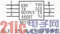
The 555 integrated circuit is an 8-pin package, dual in-line type, as shown in Figure 3, where pin 6 is called the threshold terminal (TH), which is the input of the upper comparator; pin 2 is called the trigger terminal (TR), which is the input of the lower comparator; pin 3 is the output terminal (Vo), which has two states, 0 and 1, determined by the level added to the input terminal; pin 7 is the discharge terminal (DIS), which is the output of the internal discharge tube, and has two states, floating and grounded, which is also determined by the state of the input terminal; pin 4 is the reset terminal (MR), which can make the output low when a low level is added; pin 5 is the control voltage terminal (Vc), which can be used to change the upper and lower trigger level values; pin 8 is the power supply terminal, and pin 1 is the ground terminal.
2.4 Photo module
This system uses a high-definition video head, which can be connected to a PC, has a visual monitoring interface, and can control the video head through hardware. When taking pictures, the time can be automatically stored and printed.
2.5
Overview
of LCD12864 LCD12864 with Chinese character library is a dot-matrix graphic LCD display module with multiple interface modes such as 4-bit/8-bit parallel, 2-wire or 3-wire serial, and internally contains the national standard first-level and second-level simplified Chinese character libraries; its display resolution is 128x64, with 8192 16*16-dot Chinese characters and 128 16*8-dot ASCII character sets built in. With the flexible interface mode and simple and convenient operation instructions of this module, a full Chinese human-computer interactive graphic interface can be constructed. It can display 8x4 lines of 16x16 dot Chinese characters, and can also complete graphic display. Low voltage and low power consumption are another significant feature. Compared with the same type of graphic dot-matrix LCD display module, the LCD display solution composed of this module is much simpler in terms of hardware circuit structure and display program, and the price of this module is also slightly lower than that of the graphic LCD module with the same dot matrix.
Basic characteristics
1) Low power supply voltage (VDD: +3.0~+5.5 V).
2) Display resolution: 128x64 dots.
3) Built-in Chinese character library, providing 8 192 16x16 dot matrix Chinese characters (Simplified and Traditional Chinese optional).
4) Built-in 128 16x8 dot matrix characters.
5) 2MHZ clock frequency.
6) Display mode: STN, semi-transparent, positive display.
7) Driving mode: 1/32DUTY, 1/SBIAS.
8) Viewing angle direction: 6 points.
9) Backlight mode: side high-brightness white LED, power consumption is only 1/5-1/10 of ordinary LED.
10) Communication mode: serial, parallel port optional.
11) Built-in DC-DC conversion circuit, no external negative voltage required.
12) No chip select signal required, simplifying software design.
13) Working temperature: 0~+55℃, storage temperature: -20~+60℃.
The LCD12864 liquid crystal display circuit in this system is shown in Figure 4.
[page]
3 Software DesignThe system program flow chart is shown in Figure 5.

4.1 Hardware
debugging
The hardware debugging results are shown in Table 1.
4.2 Software debugging
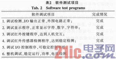
The software debugging results are shown in Table 2.

5 Conclusion
The paper mainly introduces the exhibition hall personnel registration and entry system based on MSP430F149 microcontroller, including hardware and software. The experiment shows that the system is sensitive, accurate and effective. At the same time, the system has a certain reference value for occasions where personnel registration information is required.
Previous article:Quartz crystal resonant frequency measurement system
Next article:Six source codes for basic C language programming of microcontrollers
- Popular Resources
- Popular amplifiers
- Learn ARM development(16)
- Learn ARM development(17)
- Learn ARM development(18)
- Embedded system debugging simulation tool
- A small question that has been bothering me recently has finally been solved~~
- Learn ARM development (1)
- Learn ARM development (2)
- Learn ARM development (4)
- Learn ARM development (6)
 Professor at Beihang University, dedicated to promoting microcontrollers and embedded systems for over 20 years.
- LED chemical incompatibility test to see which chemicals LEDs can be used with
- Application of ARM9 hardware coprocessor on WinCE embedded motherboard
- What are the key points for selecting rotor flowmeter?
- LM317 high power charger circuit
- A brief analysis of Embest's application and development of embedded medical devices
- Single-phase RC protection circuit
- stm32 PVD programmable voltage monitor
- Introduction and measurement of edge trigger and level trigger of 51 single chip microcomputer
- Improved design of Linux system software shell protection technology
- What to do if the ABB robot protection device stops
- Analysis of the application of several common contact parts in high-voltage connectors of new energy vehicles
- Wiring harness durability test and contact voltage drop test method
- From probes to power supplies, Tektronix is leading the way in comprehensive innovation in power electronics testing
- From probes to power supplies, Tektronix is leading the way in comprehensive innovation in power electronics testing
- Sn-doped CuO nanostructure-based ethanol gas sensor for real-time drunk driving detection in vehicles
- Design considerations for automotive battery wiring harness
- Do you know all the various motors commonly used in automotive electronics?
- What are the functions of the Internet of Vehicles? What are the uses and benefits of the Internet of Vehicles?
- Power Inverter - A critical safety system for electric vehicles
- Analysis of the information security mechanism of AUTOSAR, the automotive embedded software framework
- The difference between multilayer PCB and LTCC
- Circuit output grounding problem.
- When AD software needs to drill vias to connect the network in the inner electrical layer segmentation, what is the minimum distance between the vias and the inner electrical layer segmentation edge?
- The United States is pressing forward: blacklisting 38 Huawei subsidiaries in an attempt to block Huawei's outsourcing of chips
- 【GD32450I-EVAL】+ 06SDRAM Introduction
- 【ST NUCLEO-H743ZI Review】(1)First impressions of ST NUCLEO-H743ZI
- Keys? No more! The future of car access systems is here
- SIMETRIX/SIMPLIS simulation tutorials and examples
- Development data of National Technology N32G455
- What is IoT

 MAX916CSE-T


 京公网安备 11010802033920号