1. Verification Task
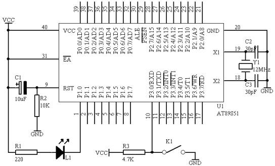
As shown in Figure 4.2.1, the monitoring switch K1 (connected to the P3.0 port) is used, and the light-emitting diode L1 (connected to the P1.0 port of the microcontroller) is used to display the switch status. If the switch is closed, the L1 light is on, and if the switch is open, the L1 light is off.
2-way schematic

Figure 4.2.1
3 Hardware connections on the system board
(1) Connect the P1.0 port in the "MCU System" area to the L1 port in the "Eight-way LED Indicator Module" area with a wire;
(2) Connect the P3.0 port in the "MCU System" area to the K1 port in the "Four-way Slide Switch" area with a wire;
4. Programming content
(1) Off state detection process
The detection of switch status by the MCU is to input the signal from the P3.0 port of the MCU, and the input signal has only two types: high level and low level. When the switch K1 is turned up, the high level is input, which is equivalent to the switch being disconnected. When the switch K1 is turned down, the low level is input, which is equivalent to the switch being closed. The MCU can use the JB BIT, REL or JNB BIT, REL instructions to complete the detection of the switch status.
(2) Output control
As shown in Figure 3, when the P1.0 port outputs a high level, that is, P1.0=1, according to the unidirectional conductivity of the light-emitting diode, the light-emitting diode L1 is off; when the P1.0 port outputs a low level, that is, P1.0=0, the light-emitting diode L1 is on; we can use the SETB P1.0 instruction to make the P1.0 port output a high level, and use the CLR P1.0 instruction to make the P1.0 port output a low level.
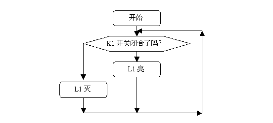
5 Sequence diagram

Figure 4.2.2[page]
6. Compile source code
ORG 00H
START: JB P3.0,LIG
CLR P1.0
SJMP START
LIG: SETB P1.0
SJMP START
END
7. C language source program
#include
sbit K1=P3^0;
sbit L1=P1^0;
void main(void)
{
while(1)
{
if(K1==0)
{
L1=0; //light on
}
else
{
L1=1; //light off
}
}
}
The above is the complete source code of the microcontroller analog switch light
Previous article:51 MCU clock and reset
Next article:Design of single-chip one-button multi-function button recognition
Recommended ReadingLatest update time:2024-11-16 16:20


 Professor at Beihang University, dedicated to promoting microcontrollers and embedded systems for over 20 years.
- Innolux's intelligent steer-by-wire solution makes cars smarter and safer
- 8051 MCU - Parity Check
- How to efficiently balance the sensitivity of tactile sensing interfaces
- What should I do if the servo motor shakes? What causes the servo motor to shake quickly?
- 【Brushless Motor】Analysis of three-phase BLDC motor and sharing of two popular development boards
- Midea Industrial Technology's subsidiaries Clou Electronics and Hekang New Energy jointly appeared at the Munich Battery Energy Storage Exhibition and Solar Energy Exhibition
- Guoxin Sichen | Application of ferroelectric memory PB85RS2MC in power battery management, with a capacity of 2M
- Analysis of common faults of frequency converter
- In a head-on competition with Qualcomm, what kind of cockpit products has Intel come up with?
- Dalian Rongke's all-vanadium liquid flow battery energy storage equipment industrialization project has entered the sprint stage before production
- Allegro MicroSystems Introduces Advanced Magnetic and Inductive Position Sensing Solutions at Electronica 2024
- Car key in the left hand, liveness detection radar in the right hand, UWB is imperative for cars!
- After a decade of rapid development, domestic CIS has entered the market
- Aegis Dagger Battery + Thor EM-i Super Hybrid, Geely New Energy has thrown out two "king bombs"
- A brief discussion on functional safety - fault, error, and failure
- In the smart car 2.0 cycle, these core industry chains are facing major opportunities!
- The United States and Japan are developing new batteries. CATL faces challenges? How should China's new energy battery industry respond?
- Murata launches high-precision 6-axis inertial sensor for automobiles
- Ford patents pre-charge alarm to help save costs and respond to emergencies
- New real-time microcontroller system from Texas Instruments enables smarter processing in automotive and industrial applications
- 【TI millimeter wave radar evaluation】+SDK development environment
- PCB News: Zhongjing Electronics plans to acquire 45% of Yuansheng Electronics for RMB 270 million to achieve horizontal integration of PCB
- How to use EPI general mode to communicate with FPGA in TM4c129 series microcontroller
- Before buying a cable fault tester, you must know about its manufacturer. How to find a good time...
- High-speed PCB design technology (Chinese)
- Buck-boost DCDC TPS63810 application in TWS earphones
- Purgatory Legend-IIC Battle
- CC3235S and CC3235SF SimpleLink Wi-Fi dual-band single-chip solutions
- Design of ESD protection structure for CMOS circuits
- 8 Common Uses of Diodes

 Wireless Sensor Network Technology and Applications (Edited by Mou Si, Yin Hong, and Su Xing)


 京公网安备 11010802033920号