Wheeled mobile robot is an important part of the robot research field. It integrates mechanics, electronics, detection technology and intelligent control. Among various mobile mechanisms, wheeled mobile mechanism is the most common. The reason why wheeled mobile mechanism is widely used is that it is easy to control its moving speed and moving direction. Therefore, it is necessary to develop a complete wheeled robot system and conduct corresponding motion planning and control algorithm research. The author designed and developed an automatic line patrol wheeled robot control system based on 5l single chip microcomputer.
2 Overall design of control system
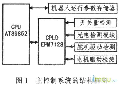
The robot control system consists of main control circuit module, memory module, photoelectric detection module, motor and steering gear drive module, etc. The block diagram of the control system is shown in Figure 1.
3 Main control module design
3.1 CPLD design
In the robot control system, it is necessary to control multiple motors and travel switches, and also to perform photoelectric detection. If all tasks are completed by the AT89S52 microcontroller, the CPU burden will be too heavy, affecting the processing speed of the system. Therefore, a CPLD is added. The model is EPM7128. It belongs to the MAX7000 series device. It includes 2 general I/O ports and 2 dedicated I/O ports. The dedicated I/O ports can be used as high-speed control signals (clock, clear and output enable, etc.) for each macro unit and input and output pins. The motor's PWM signal is also generated by it.
The pin arrangement of EPM7128 is shown in Figure 2. The output of M1P-M4P pins is PWM pulse width modulation signal, M1FB-M4FB pins are motor direction control signals, P00-P07 are connected to the PO port of the microcontroller, 100-1015 are two extended general I/O ports, S11-S17 pins are travel switch input signals, LI11-LI17 pins are photoelectric sensor input signals. CPLD is programmed in VHDL language, and the source code of part of the program that generates 1 PWM signal is as follows:
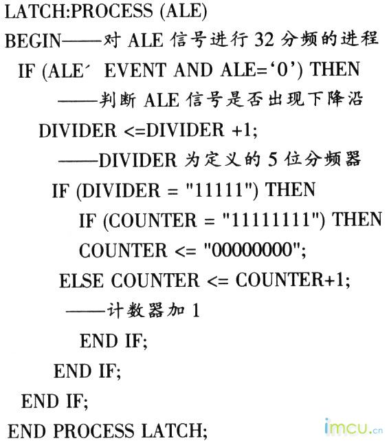
The microcontroller uses a 24MHz crystal oscillator, the frequency of the ALE signal fALE=f16=6MHz, and the frequency of the pin MlP that finally outputs the PWM signal is:


Adjusting the duty cycle of this signal can make the DC motor obtain a speed of 0-255. [page]
3.2 Expansion of the robot operation parameter memory
The robot's operation path and action can change according to the different competition situations. In this way, the Flash of the microcontroller must be erased and written every time the operation parameters are changed. In order to solve this problem, the program parameter memory is expanded to store the robot's operation path and action parameters. The expansion circuit is shown in Figure 3.
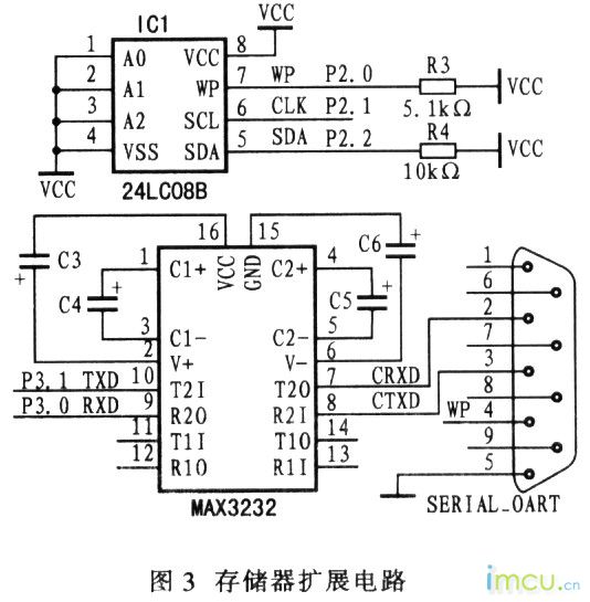
IC1 is 24LC08B, which is a serial E2PROM memory of I2E bus, and can store up to 1K bytes of data. IC2 is a MAX3232 level converter, which has a power supply voltage converter inside, which can convert the computer level to the standard TTL level, realize the data transmission between the computer and the single-chip microcomputer through the serial port, and enable the single-chip microcomputer to complete the data storage operation of 24/LC08B. When the single-chip microcomputer is running, it directly reads the robot's operating parameters from 24LC08 to control the robot's operation.
4 Photoelectric detection module design
4.1 Photoelectric detection process
The photoelectric detection module is designed to enable the robot to detect the white guide line on the ground. The photoelectric detection circuit mainly includes the transmitting part and the receiving part, and its principle is shown in Figure 4.
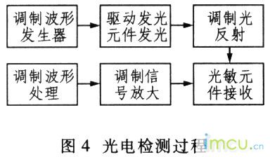
The waveform modulation of the transmitting part adopts the frequency modulation method. Due to the fast response speed of the light emitting diode, its operating frequency can reach several MHz or more than ten MHz, while the modulation frequency of the detection system is in the range of tens to hundreds of kHz, which can meet the requirements. The light source driver is mainly responsible for amplifying the modulated waveform to sufficient power to drive the light source to emit light. The light source adopts an infrared light emitting diode, which has a high operating frequency and is suitable for the emission of modulated light with a square wave waveform.
The receiving part adopts a photosensitive diode to receive the modulated light and convert the optical signal into an electrical signal. This electrical signal is usually weak and needs to be filtered and amplified before it can be processed. The amplification of the modulated signal adopts the form of AC amplification, which can separate the modulated light signal from the background light signal, providing convenience for signal processing. The modulated signal processing part identifies the amplified signal and determines the characteristics of the detected object. Therefore, the essence of this module is to separate the "AC" and useful modulated light signal from the "DC" and useless background light signal, so as to achieve the purpose of anti-interference.
4.2 Photoelectric probe
The photoelectric probe is installed at the front of the robot chassis, and a total of 5 detection points are set. Theoretically, the more and denser the detection points are, the higher the accuracy and reliability of recognition will be, but the hardware cost and software complexity will also increase accordingly. The use of this line patrol system ensures the accuracy of detection and saves hardware cost. The modulated light emitted by the light-emitting diode is reflected by the ground to the photodiode. The photocurrent generated by the photodiode changes linearly with the intensity of the reflected light. By detecting this change, it is possible to determine whether a certain detection point is above the white guide line, thereby determining the relative position of the robot and the white guide line.
5 Motor drive module
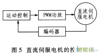
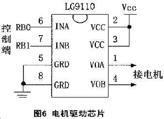
The driving parts of the robot are mainly motors and servos, both of which can be regulated and controlled by PWM. According to the feedback signal of the pulse encoder, the motion state of the robot is controlled in real time. The control principle of the DC servo motor is shown in Figure 5. Adjustment: The PWM signal can quickly adjust the angle of the servo, thereby realizing the direction control of the robot.
6 Conclusion
The automatic line patrol wheeled robot control system based on the 5l type single chip microcomputer runs smoothly and reliably, and has strong anti-interference ability. It not only meets the design requirements of the robot competition, but also builds a good control platform for intelligent robots.
Previous article:Comparison between MSP430 series and 89C5l series
Next article:Design method of frequency meter based on single chip microcomputer 89C51,
Recommended ReadingLatest update time:2024-11-16 20:35


 Professor at Beihang University, dedicated to promoting microcontrollers and embedded systems for over 20 years.
- Innolux's intelligent steer-by-wire solution makes cars smarter and safer
- 8051 MCU - Parity Check
- How to efficiently balance the sensitivity of tactile sensing interfaces
- What should I do if the servo motor shakes? What causes the servo motor to shake quickly?
- 【Brushless Motor】Analysis of three-phase BLDC motor and sharing of two popular development boards
- Midea Industrial Technology's subsidiaries Clou Electronics and Hekang New Energy jointly appeared at the Munich Battery Energy Storage Exhibition and Solar Energy Exhibition
- Guoxin Sichen | Application of ferroelectric memory PB85RS2MC in power battery management, with a capacity of 2M
- Analysis of common faults of frequency converter
- In a head-on competition with Qualcomm, what kind of cockpit products has Intel come up with?
- Dalian Rongke's all-vanadium liquid flow battery energy storage equipment industrialization project has entered the sprint stage before production
- Allegro MicroSystems Introduces Advanced Magnetic and Inductive Position Sensing Solutions at Electronica 2024
- Car key in the left hand, liveness detection radar in the right hand, UWB is imperative for cars!
- After a decade of rapid development, domestic CIS has entered the market
- Aegis Dagger Battery + Thor EM-i Super Hybrid, Geely New Energy has thrown out two "king bombs"
- A brief discussion on functional safety - fault, error, and failure
- In the smart car 2.0 cycle, these core industry chains are facing major opportunities!
- The United States and Japan are developing new batteries. CATL faces challenges? How should China's new energy battery industry respond?
- Murata launches high-precision 6-axis inertial sensor for automobiles
- Ford patents pre-charge alarm to help save costs and respond to emergencies
- New real-time microcontroller system from Texas Instruments enables smarter processing in automotive and industrial applications
- 5 days left to register | Full schedule of the annual AIoT Developer Conference! 19 technical lectures full of practical information!
- Please tell me how to protect the gas meter using Hall device from strong magnetism, and whether it has one or two Hall devices.
- I don't know how many days I have been learning HFSS
- [STM32F769Discovery development board trial] USB-HS HID simple transmission and reception evaluation
- There is a problem with testing multimedia
- Use chips that support the BLE 4.2 specification to implement application system design
- TMS320F2812 advice
- EEWORLD University Hall----Parallel Computing
- CPU temperature exceeds the limit
- Infrared ToF technology will significantly improve the performance and reliability of proximity sensors

 Wireless Sensor Network Technology and Applications (Edited by Mou Si, Yin Hong, and Su Xing)


 京公网安备 11010802033920号