1 Main features of EM78P447S
The EM78 series microcontroller is an 8-bit cost-effective microcontroller manufactured by Taiwan Elan Electronics Co., Ltd. using CMOS technology. This series of microcontrollers generally have built-in watchdog counter (WDT), RAM, ROM, programmable timer/counter, prescaler and 5-layer stack. Most instructions of this series of devices only require two oscillation cycles, and it also has functions such as internal and external interrupts, low-voltage detection reset, programmable I/0, internal pull-up resistor, open-collector output, and SLEEP mode. In addition, the EM78P447S microcontroller also has the advantages of simple programming, fast speed, low power consumption, and low cost, and can be widely used in toys, home appliances, industrial control, etc.
The main performance features of EM78P447S are as follows:
●Working voltage range: 2.5-5.5V;
●Allowable temperature range: 0-70°C;
●Operating frequency range:
Quartz oscillation type: the range is DC-20MHz at 5V,
The range at 3V is DC-8MHz;
RC oscillation type: the range is DC-4MHz at 5V;
The range at 3V is DC-4MHz;
●One-time programmable ROM up to 4K X 13bit;
●Internal RAM is 148 X 8bit;
●With 5-layer stack;
●Contains a watchdog timer (WDT) that can be programmed by itself and an 8-bit prescaler;
●Has 24 bidirectional three-state I/O pins;
●I/O in sleep state can be planned;
●There are ten I/O pins with boost resistance and wake-up CPU;
●There are two I/O pins with R-Option function. Through the R-Option function, when the same microcontroller is placed in two or more application programs, an input pin can be used to determine which program to select. In other words, the R-option function is to set selectable pull-down resistors on certain two I/0 pins of EM78P447S, so that the status of the pin can be judged by whether the user connects an external pull-down resistor (usually 510kΩ), and then the running direction can be determined. a program;
●There are two output pins that can be programmed as open collectors;
●The signal source and trigger source can be selected through an 8-bit timer/counter (TCC), and 8-bit prescaler can be performed;
●With overflow interrupt function;
●Has functions such as power-on reset, low-level detection reset, RESET pin input low-level reset, WDT timeout overflow reset, etc.;
●Most instructions only require two oscillation cycles;
●Has low-level sleep mode;
●Has TCC overflow interrupt, external INT pin input pulse interrupt and INT instruction execution software interrupt functions;
●Using 32-pin DIP package.
2 Pin functions and registers of EM78P447S
2.1 Pin arrangement of EM78P447S
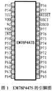
Figure 1 shows the pin arrangement of EM78P447S. The functions of each pin are as follows:
 |
TCC: external counting input pin;
OSCO: oscillation output pin;
VDD: Positive power input pin;
OSCI: crystal oscillator or RC oscillator input pin;
NC: empty foot;
BESET: Reset input terminal, active low level;
VSS: ground pin;
INT: External interrupt input pin, falling edge input is valid;
P50-P57: Bidirectional I/O pins;
P60-P67: Bidirectional I/O pins, which can be programmed with internal boost resistors through software;
P70-P77: Bidirectional I/O pins, among which P74 and P75 can be programmed with internal boost resistors through software; P76 and P77 can be set as open-collector output pins through software; P70 and P71 can be used as R-Option Enter the pin.
2.2 Registers in EM78P447S
EM78P447S contains 9 operation purpose registers. Among them, indirect addressing register R0 (IAB), timer/counter R1 (TCC), program counter R2 (PC), status register R3 (STATUS), RAM selection register R4 (RSR), I/O port register R5 (PORT5), The addresses of the eight registers including R6 (PORT6) and R7 (PORT7) are 00H-07H in sequence, while the address of the interrupt status register R3F (1SR) is 3FH.
Among the 148 general-purpose registers (RAM) of EM78P447S, there are registers with addresses 08H-1FH and 4 register groups with addresses 20H-3EH (the 4 page addresses are determined by bits 6 and 7 of R4).
In addition, there are 7 special function registers in EM78P447S. These include accumulator A, control register CONT, input/output control registers IOC5, IOC6, and IOC7 (controlling the input/output modes of port5, port6, and port7 respectively), WDT control register IOCE, and interrupt mask register IOCF.
2.3 Introduction to instructions of EM78P447S
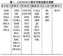
The EM78P447S microcontroller has a total of 45 words and 58 instructions. These 58 instructions include 19 logic instructions, 11 arithmetic operation instructions, 4 bit instructions, 4 transfer instructions, 10 control instructions and 10 jump instructions. Table 1 gives the classification of these instruction words according to their functions.
The instructions of the EM78P447S microcontroller mainly have the following features:
●Except for the instruction that changes the program counter, which requires two instruction cycles, the other instructions are all single instruction cycles;
●Each bit of the register can be directly set, cleared or tested by bit-type instructions;
●The I/O register corresponding to the IO pin can also be accessed as a general register. In other words, the instructions used to access general registers and I/O are exactly the same.
3 Application in DC motor remote control system
The remote control system designed using EM78P447S as the main controller can realize remote control of forward, reverse and stop rotation of the DC motor. The remote control system consists of three parts: a transmitting module, a receiving input module and a microcontroller processing output module.
3.1 Launch module
The transmitting module in the remote control system designed by the author uses a 3V working voltage. There are three ping-pong keys KO, K1, and K2 on the circuit board, which can be used to control the forward, reverse, and stop operations of the motor respectively. When it is necessary to transmit, the dedicated chip PT2248 for transmitting and the peripheral amplifier circuit are used to amplify the signal, and then infrared transmission can be carried out. The schematic diagram of its hardware circuit is shown in Figure 2.
 |
3.2 Receive input module
The receiving module in this remote control system uses a 5V working voltage, and there is a receiver on the circuit board that can be used to receive the signal transmitted by the transmitting module. An amplifier circuit can be used to amplify the received signal and transmit it to the receiving dedicated chip PT2249A, and then process it through 74LS04 before sending it to the microcontroller. Three light-emitting diodes can be used to respectively correspond to the three buttons of the transmitting module to display operations. When a key is pressed, the corresponding light-emitting diode emits light. The hardware circuit is shown in Figure 3.
 |
3.3 Microcontroller processing output module
The single-chip microcomputer processing output module uses a 5V working voltage. The three ping-pong keys K3, K4, and K5 on the module correspond to the three keys KO, K1, and K2 on the transmitting module, which can be used to control the forward, reverse, and reverse rotation of the motor. stop. These three keys can replace KO, K1 and K2 for operation when the remote control has problems or is lost, so it is very convenient and practical.
The P5.0-P5.2 pins on the microcontroller are respectively used as the signal input terminals for the motor's forward rotation, reverse rotation and stop. The P6.0 and P6.1 pins are respectively used as the signal output terminals for the motor's forward rotation and reverse rotation. To stop the motor, just send the invalid signal to P6.0 and P6.1. After the output signal of the microcontroller is reversed by the 74LS04 and sent to the ULN2003A for amplification, the relay can be driven to make the DC motor operate accordingly.
In addition, two light-emitting diodes can be used to display the operation. This way, when the motor is running forward or reverse, one of the diodes will light up, and when the stop button is pressed, neither will light up. Its hardware circuit is shown in Figure 4.
 |
4 System software design
This design uses the development tool EMC that comes with the EM series microcontroller as the programming tool, and the main program continuously monitors the status of the ping-pong keys in a loop. When a button is pressed and released, its corresponding motor is started, and then the system returns to detect the status of the button to determine whether to maintain the operating state or transfer to other states.
It should be noted that when the mechanical switch is pressed or released, the button will bounce on the contact due to mechanical elasticity. This rapid jump will be completely detected by the CPU, so there will be an error situation where the user only presses the switch once, but is considered by the CPU to have been pressed many times. In order to avoid this misjudgment phenomenon, a delay can be used to deal with this bouncing problem during design. When the software detects that the switch is pressed, it delays the detection for a period of time and then detects it again to avoid the bounce time. This bounce usually occurs between 20ms and 50ms after the switch is pressed, so as long as it avoids Just turn on this period of time without reading the signal of the input pin. The software process is shown in Figure 5.
 |
references
1. Deng Jincheng. Introduction and implementation of EM78447
2. Wu Jiansheng. EM78154/x56/x57 series 8-bit microcontroller principles and applications. Fuzhou Xinyuan Electronic Technology Research Institute, 1998, 3
Previous article:EM78P447S microcontroller and its application in DC motor infrared remote control system
Next article:Simple intelligent robot designed based on AT89C51 microcontroller
Recommended ReadingLatest update time:2024-11-16 16:40

 Professor at Beihang University, dedicated to promoting microcontrollers and embedded systems for over 20 years.
- Innolux's intelligent steer-by-wire solution makes cars smarter and safer
- 8051 MCU - Parity Check
- How to efficiently balance the sensitivity of tactile sensing interfaces
- What should I do if the servo motor shakes? What causes the servo motor to shake quickly?
- 【Brushless Motor】Analysis of three-phase BLDC motor and sharing of two popular development boards
- Midea Industrial Technology's subsidiaries Clou Electronics and Hekang New Energy jointly appeared at the Munich Battery Energy Storage Exhibition and Solar Energy Exhibition
- Guoxin Sichen | Application of ferroelectric memory PB85RS2MC in power battery management, with a capacity of 2M
- Analysis of common faults of frequency converter
- In a head-on competition with Qualcomm, what kind of cockpit products has Intel come up with?
- Dalian Rongke's all-vanadium liquid flow battery energy storage equipment industrialization project has entered the sprint stage before production
- Allegro MicroSystems Introduces Advanced Magnetic and Inductive Position Sensing Solutions at Electronica 2024
- Car key in the left hand, liveness detection radar in the right hand, UWB is imperative for cars!
- After a decade of rapid development, domestic CIS has entered the market
- Aegis Dagger Battery + Thor EM-i Super Hybrid, Geely New Energy has thrown out two "king bombs"
- A brief discussion on functional safety - fault, error, and failure
- In the smart car 2.0 cycle, these core industry chains are facing major opportunities!
- The United States and Japan are developing new batteries. CATL faces challenges? How should China's new energy battery industry respond?
- Murata launches high-precision 6-axis inertial sensor for automobiles
- Ford patents pre-charge alarm to help save costs and respond to emergencies
- New real-time microcontroller system from Texas Instruments enables smarter processing in automotive and industrial applications
- EEWORLD University - Understanding and comparing high-speed analog-to-digital (ADC) and digital-to-analog converter (DAC) converter architectures
- Comprehensively explain the relationship between power supply PCB layout and EMC from nine aspects!
- Ask about copper plating and splitting power planes
- SHT31 Review + Unboxing
- MSP430: Input Capture
- High Voltage Impedance Tuning Quick Guide
- K210 face recognition environment construction process
- Charge up! The latest generation of ACF UCC28782 ultra-small fast charging adapter!
- Proteus simulation experiment of single chip microcomputer communication
- 【TI recommended course】#Power system design tools#

 西门子S7-12001500 PLC SCL语言编程从入门到精通 (北岛李工)


 京公网安备 11010802033920号