1 Introduction
At present, vector control (VC) and direct torque control (DTC) have been recognized as high-performance AC variable frequency speed regulation technologies. The vector control system adopts rotor flux orientation to achieve the decoupling of the stator current torque component and the flux component. The speed and flux regulators (usually PI regulators) can be designed separately according to linear theory to implement continuous control, thereby obtaining a wider speed regulation range, but the system is easily affected by the change of rotor parameters. The direct torque control system abandons the more complex rotating coordinate transformation, directly calculates the electromagnetic torque and stator flux in the stator stationary coordinate system, and uses double-position bang-bang control to adjust the torque and flux. It is less affected by motor parameters and has a fast torque response. However, since bang-bang control itself belongs to P control, torque pulsation is inevitable, affecting the low-speed performance of the system. The ISR (Indirekte Selbst Regelung) control strategy introduced in this paper can effectively reduce the torque pulsation in direct torque control, and has good low-speed performance and dynamic and static characteristics.
2 Dynamic model of asynchronous motor
The voltage equation and electromagnetic torque equation of the asynchronous motor in the stator two-phase stationary coordinate system (α, β) can be expressed as:
uαs=rsiαs+pψαs (1)
uβs=rsiβs+pψβs (2)
 (3)
(3)
Where: uαs, uβs, iαs, iβs, ψαs, ψβs are the α and β axis components of the stator side voltage, current and flux in the α and β coordinate systems respectively: rs is the stator resistance; np is the number of motor pole pairs; p is the differential operator; is the motor leakage inductance as a constant; θ is the angle between the stator flux and the rotor flux.
From equations (1) and (2), we can get that the stator flux in the stator two-phase stationary coordinate system can be expressed as:
![]() (4)
(4)
![]() (5)
(5)
The main circuit diagram of direct torque control is shown in Figure 1.

Figure 1 Main circuit diagram of direct torque control
The 8 switching states of the inverter correspond to 8 sets of voltage vectors, as shown in Table 1 [1].
Table 1 Voltage vector table

Table 2 Inverter voltage vector selection table

In order to facilitate the control of stator flux and electromagnetic torque, we divide the flux space vector into 6 equal areas. The division principle is:
 (6)
(6)
k is the sector number, k=1,2,3,4,5,6, as shown in Figure 2. In each sector, different voltage vectors are selected for different conditions of flux and torque. Figure 3 is a bang-bang control scheme.
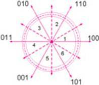
Figure 2 Sector and voltage vector diagram
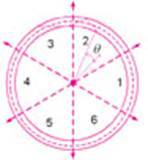
Figure 3 bang-bang control
3 Traditional bang-bang hysteresis control strategy
3.1 Control of stator flux
The calculation model of stator flux can be constructed by equations (4) and (5), so as to obtain the actual value of stator flux ψs. Figure 4 is the stator flux hysteresis control diagram. Figure 5 is the electromagnetic torque hysteresis control diagram. Figure 4 Stator flux hysteresis control diagram Figure

5

Electromagnetic torque hysteresis control diagram
The input of the flux hysteresis is the difference between the flux set value ψs* and the actual flux value ψs, and the output is the flux switching signal hψ, ±ε is the hysteresis width. The flux error is defined as: δψ=ψs*-ψs, then the control method of the flux regulator is as follows:
(1) When δψ≥ε, hψ=1, at this time, the voltage vector is selected to increase |ψs|.
(2) When δψ≤-ε, hψ=-1, at this time, the voltage vector is selected to reduce |ψs|.
3.2 Control of electromagnetic torque
The input of the torque regulator is the difference between the torque given value te* and the actual torque value te, and the output switching signal hte is the tolerance width ε. The regulator adopts a discrete three-point adjustment method, and the torque error is:
δt= te*- te.
The control law of the torque regulator is as follows:
when δt≥ε, hte=1;
when |δt|≤ε, hte=0;
when δt<-ε, hte=-1;
after obtaining the output signals of flux and torque, we can select the corresponding stator voltage vector according to Table 2.
When the stator flux and electromagnetic torque reach the upper and lower limits of the hysteresis loop, the controller adjusts the stator voltage vector so that the flux and torque meet the set requirements as shown in Figure 3.
4 New control scheme based on pi regulator
For equations (4) and (5), we can approximate by ignoring the stator resistance:
![]() (7)
(7)
![]() (8)
(8)
By transforming (7) and (8), we can obtain:
![]() (9)
(9)
We can see that when the stator resistance voltage drop is ignored, the change of the stator flux per unit time is the voltage vector applied to the stator side, that is, the trajectory of the flux can be determined by the stator voltage vector per unit time [2][3], as shown in Figure 6.
In hysteresis control, the regulator will only adjust when the torque or flux reaches the set hysteresis width. In the new scheme, the regulation of the stator flux and electromagnetic torque is performed per unit sampling time, which makes the regulation more precise and reduces the torque pulsation. In addition, since the regulation of the stator side voltage vector is performed per unit time, the switching frequency of the inverter is constant, which solves the disadvantage of the non-fixed switching frequency of traditional DTC control. The structure of replacing hysteresis control with pi regulator is shown in Figure 7.
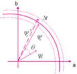
Figure 6 Flux change per unit time

Figure 7 Stator flux pi regulator control
The specific control strategy of flux regulation is: the calculated value of flux is compared with the given value. If the pi output is greater than zero, hψ=1 is set. At this time, the stator flux needs to be increased until the pi output is zero. When the pi output is less than zero, hψ=-1 is set. At this time, the flux needs to be reduced until the pi output is zero. Similarly, the calculated value of torque is compared with the given value. For torque regulation, if the pi output is greater than zero, hte=1 is set. At this time, the electromagnetic torque needs to be increased until the pi output is zero. When the pi output is less than zero, hte=-1 is set. At this time, the flux needs to be reduced until the pi output is zero.
The specific implementation in matlab is shown in Figure 8. The torque regulator has the same structure as the flux regulator.
Figure 8
Comparison and analysis of simulation waveforms
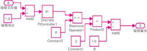
of flux regulator 5 in matlab
Matlab simulation comparison of direct torque bang-bang control and pi control of asynchronous motors. Under the same sampling step, the torque change of the control process is shown in Figure 9. The motor first reaches the set speed with the maximum torque and then stabilizes. In the comparison between pi control and bang-bang control, we can clearly see that the torque pulsation of pi control is much smoother than that of bang-bang control, as shown in Figure 10.
Figure 9 Torque waveform of asynchronous motor direct torque control
Figure 10 Enlarged view of torque waveform of bang-bang control and pi control
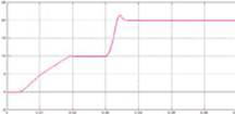
From the speed response curve in Figure 11, it takes 5ms for the speed to increase from 10rad/s to 20rad/s, indicating that the system has good dynamic and static characteristics.
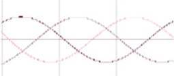
From Figure 12 (a) and Figure 12 (b), we can see that the current curve based on pi control is much smoother than the current curve based on bang-bang control, which shows that pi control is superior to hysteresis control not only in torque control but also in current.
Figure 11 Speed response curve of asynchronous motor direct torque control
Figure 12 (a) Current curve of pi control
Figure 12 (b) Current curve of bang-bang control
6 Conclusion
When the system is unloaded, the use of pi regulator instead of bang-bang hysteresis controller can effectively reduce the torque pulsation in the direct torque control scheme, effectively suppress current harmonics, have good low-speed performance and dynamic and static characteristics, facilitate digital implementation, and greatly improve the direct torque control performance.



Previous article:Dual-motor control technology simplifies energy-efficient appliance design
Next article:Control scheme of soft start of main motor of shearing machine
- Popular Resources
- Popular amplifiers
- Molex leverages SAP solutions to drive smart supply chain collaboration
- Pickering Launches New Future-Proof PXIe Single-Slot Controller for High-Performance Test and Measurement Applications
- CGD and Qorvo to jointly revolutionize motor control solutions
- Advanced gameplay, Harting takes your PCB board connection to a new level!
- Nidec Intelligent Motion is the first to launch an electric clutch ECU for two-wheeled vehicles
- Bosch and Tsinghua University renew cooperation agreement on artificial intelligence research to jointly promote the development of artificial intelligence in the industrial field
- GigaDevice unveils new MCU products, deeply unlocking industrial application scenarios with diversified products and solutions
- Advantech: Investing in Edge AI Innovation to Drive an Intelligent Future
- CGD and QORVO will revolutionize motor control solutions
- Innolux's intelligent steer-by-wire solution makes cars smarter and safer
- 8051 MCU - Parity Check
- How to efficiently balance the sensitivity of tactile sensing interfaces
- What should I do if the servo motor shakes? What causes the servo motor to shake quickly?
- 【Brushless Motor】Analysis of three-phase BLDC motor and sharing of two popular development boards
- Midea Industrial Technology's subsidiaries Clou Electronics and Hekang New Energy jointly appeared at the Munich Battery Energy Storage Exhibition and Solar Energy Exhibition
- Guoxin Sichen | Application of ferroelectric memory PB85RS2MC in power battery management, with a capacity of 2M
- Analysis of common faults of frequency converter
- In a head-on competition with Qualcomm, what kind of cockpit products has Intel come up with?
- Dalian Rongke's all-vanadium liquid flow battery energy storage equipment industrialization project has entered the sprint stage before production
- Allegro MicroSystems Introduces Advanced Magnetic and Inductive Position Sensing Solutions at Electronica 2024
- Car key in the left hand, liveness detection radar in the right hand, UWB is imperative for cars!
- After a decade of rapid development, domestic CIS has entered the market
- Aegis Dagger Battery + Thor EM-i Super Hybrid, Geely New Energy has thrown out two "king bombs"
- A brief discussion on functional safety - fault, error, and failure
- In the smart car 2.0 cycle, these core industry chains are facing major opportunities!
- The United States and Japan are developing new batteries. CATL faces challenges? How should China's new energy battery industry respond?
- Murata launches high-precision 6-axis inertial sensor for automobiles
- Ford patents pre-charge alarm to help save costs and respond to emergencies
- New real-time microcontroller system from Texas Instruments enables smarter processing in automotive and industrial applications
- EEWORLD University Hall----Analog Integrated Circuit Design (Li Zhangquan, Shanghai Jiaotong University)
- Request a free ZVS buck-boost evaluation board!
- USB TYPE C interface problem urgent help
- Notice on the extension of ON Semiconductor and Avnet IoT Innovation Design Competition
- Can't find header file when compiling
- RTC timekeeping function + GPIO control LCD12864 display
- On-chip memory resources of RSL10
- UART Protocol Timing Summary
- NXP Smart Car Northeast Competition First Prize, we will open source after the competition
- Non-inverting proportional amplifier feedback resistor setting

 5962-8856502CX


 京公网安备 11010802033920号